|
HBR-2018 HF 160 to 6 meter High Performance All-Mode
Transceiver
PAGE UPDATES
December 2018: The re-build of the original HBR-2000 transceiver is now
complete and renamed the HBR-2018.
In the HBR-2000 page shown in the menu above I described a HF (160 to 6
meters) High Performance Transceiver that I built and completed in 2000. The
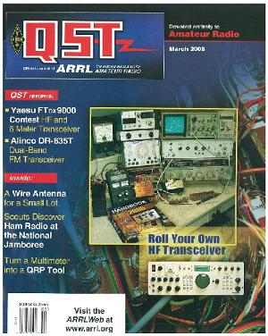
March 2006 issue of QST contained a brief description of this transceiver.
In early 2015 I decided to rebuild some of the modules in the orginal HBR-2000. The reason for re-building the HBR-2000
was to encorporate what I learned when building the
original version, both electrically and mechanically. Some of the original
surplus components (mainly relays) were failing plus shielding between the
bandpass filters was poorly done resulting in several birdies especially on
12 and 10 meters that were objectional. In addition
I felt I needed to make the individual modules more accessible for further
improvements or repairs if needed.
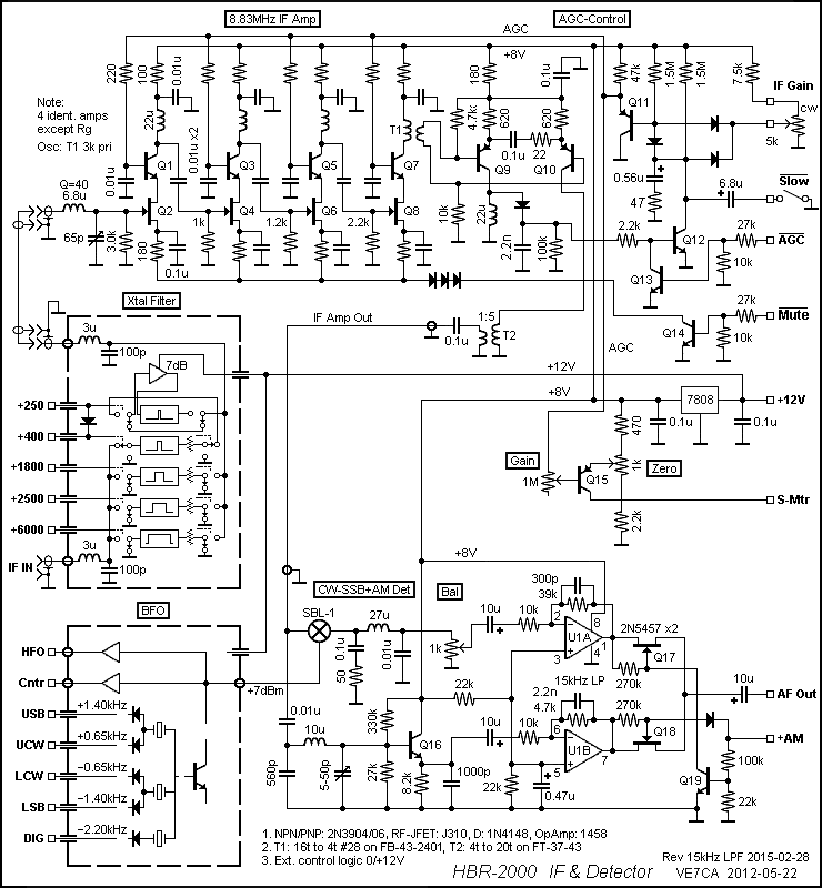
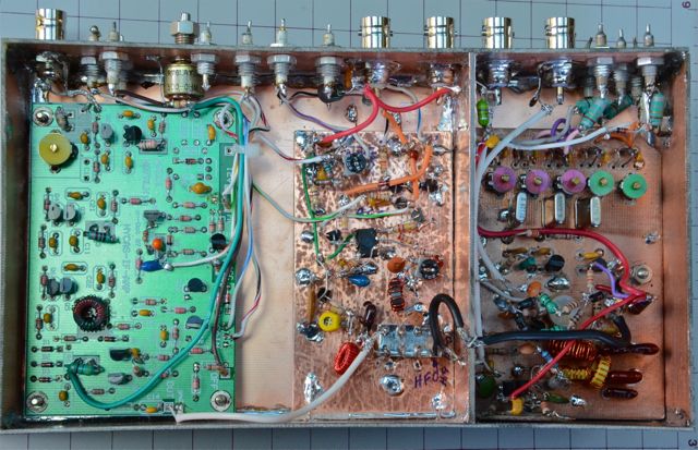
REVISED IF, DETECTOR AND AUDIO MODULES:
1. IF-Detector Module
This module has a diode switched 5-frequency (CW+/-, USB, LSB, Digital) BFO
and a relay switched 5-bandwidth (250/400/1800/2500/6000Hz BW) crystal filter
included (all well shielded). The BFO is amplified to +7dBm for product detector,
150 mV for the transmitter balanced modulator and a low level output for the
frequency counter. Since the BFO circuit is in the IF box, I fully enclosed
the BFO circuit to elliminate BFO leakage into the IF circuit.
The filter output connects to the IF input of a modified version (4 stage) of
Wes HaYward, W7ZOI's hybrid Bipolar/FET cascode amplifier. The extra stage makes the amplifier
gain suitable for normal 1st converter outputs and termination in a
double-balanced diode mixer and AM detector with outputs of reasonable
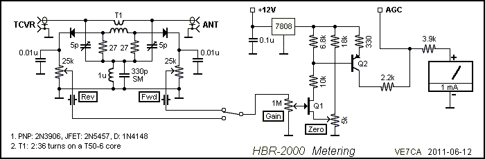
magnitude. A DC amplifier was added to drive an S-meter with the AGC signal
(see Meter schematic below which includes Fwd/Ref
detector cct.). The output to the detector and some
control circuitry is also slightly different to the W7ZOI design. It is
reasonably stable but care in its construction and careful grounding and
probing for instability are recommended.
The AM and CW/SSB detectors produce low undistorted audio signals that are
15kHz low-pass filtered (to remove wideband noise without affecting AF
response) and audio amplified to a level suitable for the following Audio
Module. Mode selection is done using FET switches. The Bal control is
adjusted with AGC off and linear input level, so that 60% AM @ 1kHz produces
the same output as a 1kHz CW tone.
System designers should note that the CW sensitivity at the IF input will be
3dB worse than what it would be if the IF had selectivity to reject the BFO
image. Having selectivity in the IF (this IF amp is over 100kHz wide) is a
trade off of AGC performance, stability and distortion. With this in mind,
when I rebuilt the IF stage I added a 2.5 KHz BW Crystal filter at the end of
the last IF stage. This filter also restricts the noise bandwidth of the IF
energy reaching the detectors. The system sensitvity
is determined by the first active stage and the losses that preceed it. So if you are interested in sensitivity (or
IMD/cross-modulation etc.), that's where the action is. The signal coming
from the stage before primary filtering will over power the BFO image as each
stage's input noise overpowers the output noise of each following stage. This
receiver was designed to have high overall performance including T/R delay,
AGC dynamics, IMD and baseband frequency response (flat 100 to 3000Hz limited
only where absoloutely necessary). An AM detector
is included for both amateur and non-amteur
reception. Signal crispness, listening and tuning comfort was a factor in the
design. The IF module output is about 0.35Vpp at -90dBm input (before 400Hz Xtal filter of 10dB loss) CW with IF gain full and no AGC
and the IF amp gain is -94dBm to 350mVpp or 89dB.
IF-Detector
Schematic.
Meter Schematic.
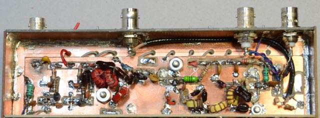
IF-Detector Module.
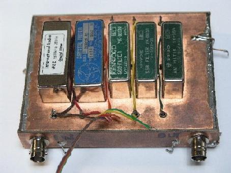
IF Filters
I had several Kenwood 8.83 MHz crystal filters on hand and decided to use
them in the receiver. The picture below shows the construction and mounting
of the filters. A shield was inserted between the input and output terminals
of the filters inside the PC box providing measured stop band attenuation in
excess of 100 dB. Again all control leads go
through feed-thru capacitors and the input and output RF points employ BNC
connectors.
I chose relays instead of diodes to switch between the different filters as I
did not what to chance introducing IMD via diodes into the receiver. The BW
of the filters I had on hand were, 6kHz, 2.5kHz, 1.8kHz, 400Hz and 250Hz.
When the 250Hz filter is selected, the 400Hz filter is automatically inserted
in series with the 250Hz filter along with an amplifier which compensates for
the extra loss of the two filters in series. Also, resistive pads are added
to the output of all the filters except the 6 KHz filter to compensate for
the different losses of each filter. I can switch between filters when
listening to a signal and the audio output level does not change.
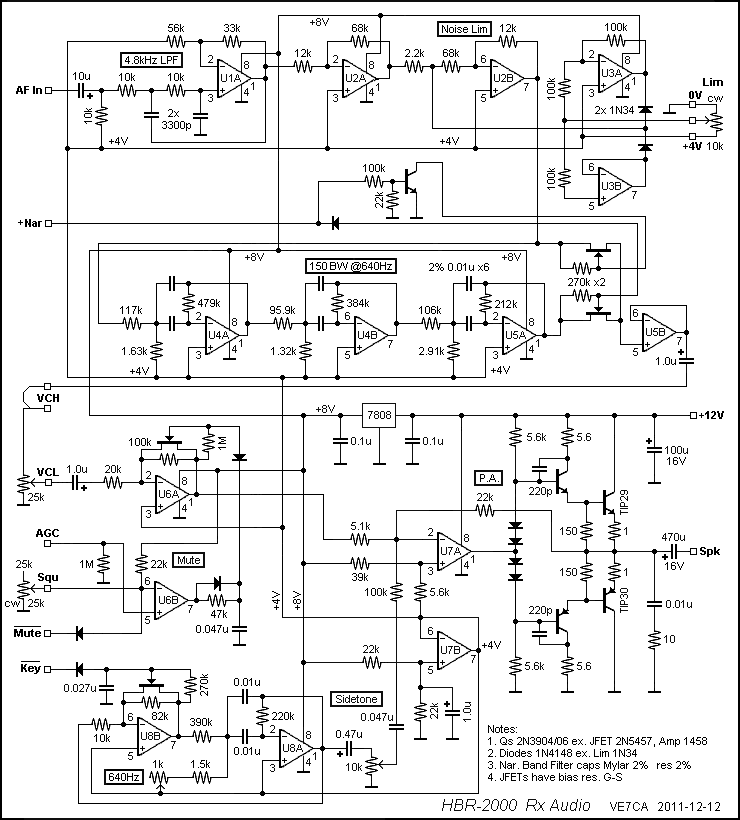
4. Audio Module
In 2011 I redesigned and built new Audio and IF modules for the HBR-2000. The
product and AM detectors are designed for good audio quality (low distortion
and flat 100HZ to 3000Hz). Since I intended to include the capability to
receiver AM, I added transistor switches to select either the product
detector or the AM detector. This module provides x10 voltage gain and at
least 2 watt 4-ohm speaker drive with 100mVpp in. Performance is degraded
very little down to 9V supply.
The first filter has a gain of x1.6 and sets the input impedance to about 10k
ohms and the band limit to 4.8kHz (that is, flat from 100 to 3000Hz) so that
the bandwidth is well defined before signals are processed and so that
measurements made at the output will include only the audio band.
The next 4 op-amps make up a variable threshold hard limiter with a x6
pre-amplifier, x1/6 limiter/post attenuator (3 op-amps). This limiter was
designed to for unity gain by having a x6 amplification/attenuation with a
diode clipper in the middle. When not in use, the Lim control is set
CCW for a high limiting level. At Max/Min limiting the limiter diodes clip as
low/high as 1.2/6Vpp or about 0.75/4Vpp(7dB range) at module input. The IF
gain control is used to determine where the signal is compared to the limit
threshold. Having AGC within the limiter and electronically switching it was
considered not worth the trouble. Since it has unity gain, it could be
switched out or not included.
Next is a 150Hz BW at 640 Hz band-pass filter which is enabled/disabled by
control input Nar being high/low(ex. 8V/0V). The
capacitors(2%)/resistors should be high quality and high Q and could be
chosen for accuracy from a group. The filter is 6th order and pole postions are quite sensitive and, like the limiter, has
unity gain and need not be included if not required. However after including
it I have found it very beneficial. In situations where signals are right at
the noise level, switching in the 150Hz BW filter significantly reduces noise
on either side of the filter BW which in most cases causes the signal to jump
out of the noise. The output passes through a jumper or external filters or
other circuitry if desired and finally to the volume control.
The design of such filters is easy if you join our Design group (see Design
in the Home menu above). In Design, go to Active Filters and you can use the
program to design a filter to your liking. Adjusting the bandwidth, centre frequency and capacitor values, I designed an
audio filter employing 3 op amps with a BW of 150 Hz centred
at about the frequency I like listening to, 650 Hz. I used 5% resistors but
selected them to be within 1% of design values and selected a group of 0.01uF
caps within 1% of each other resulting in a 640Hz centre.
The measured response was the same as the design and it does not ring!
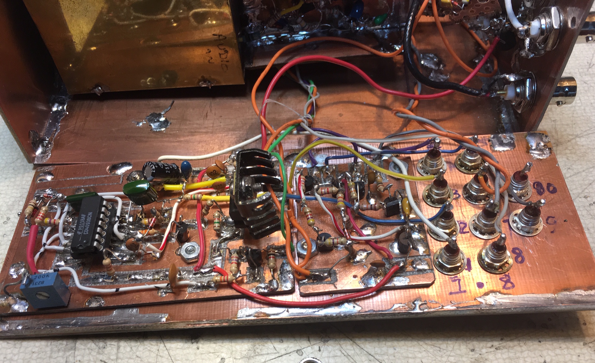
The amplifier section preamp has a x5 gain and is gated on/off by the Squ and Mute circuits with a 2ms unmute
delay. I did have a connection to Squ from
the AGC but plan to make a new improved circuit. The Mute control
input is low to mute and comes from an early signal in TX/RX control. The
power amplifier has a gain of x4 and a low quiescent drain and distortion
using inexpensive tab mount transistors. Low-level circuits in the module are
based on a +8V and +4V mid supply to allow operation over a wide variation of
the 12v main supply. The 4 diodes provide suitable bias and DC coupling to
the final amplifier. There is also a barely oscillating (near critical gain)
shaped sinusoidal sidetone oscilator
with several ms of start and finish shaping for a
very smooth sound but the gain may have to be set by adjusting the 82k
resister across the FET switch to get desired shape (or just to get it
oscillating if caps are low Q!). A 4-ohm or 8-ohm speaker works fine and give
2 watts (4-ohms) of clean AF power.
Audio
Module Schematic.
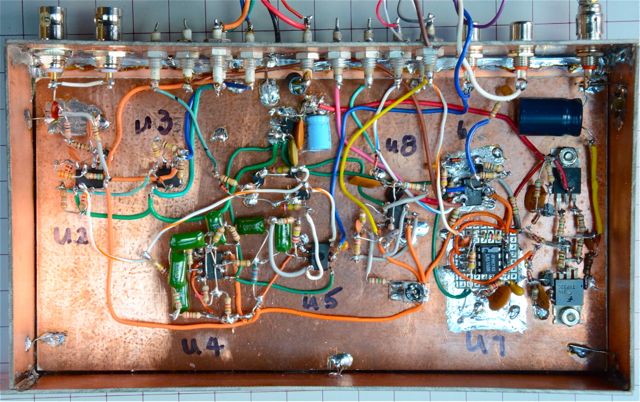
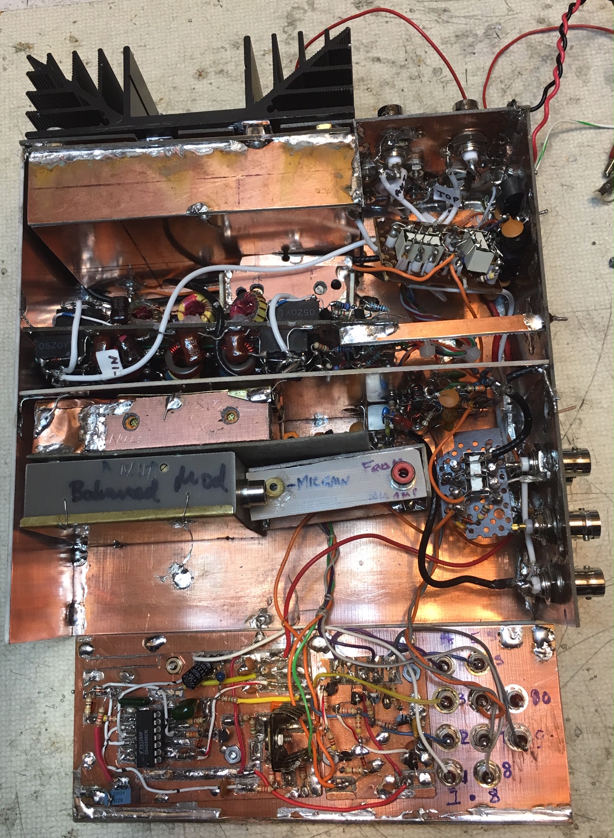
Audio Module Photo.
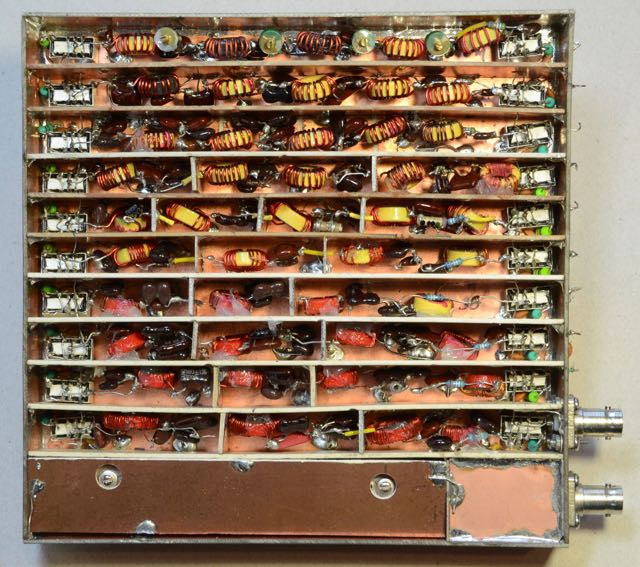
BAND PASS
FILTER MODULE:
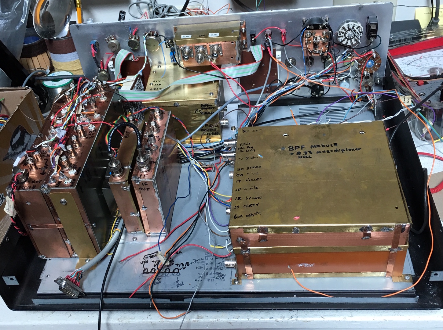
Here is a photo of the new BPF module.
BPF Module
All the filters used in the HBR-2000 and the HBR-2018 were derived using the
program listed in the main menu under the Design Page. If you wish access to
this program please send me an email.
The new BPF filter modular is smaller in size. The dimenions
are 173 mm by 178 mm with a depth of 30 mm. It is 1/3rd smaller than the
module in the HBR-2000. As well, some of the individual BPF's encorporate more stages of filtering to achieve improved
stop band attentuation. The relays that I had used
in the HBR-2000 were cheap and had begun sticking when closed or releasing
very slowly. The new relays I chose are OMRON G6S-2-Y12VDC. The relay
contacts are listed as being composed of (AG)AU which consist of a silver
base and gold shell. Hopefully over a the long term this will reduce the
chances of the contacts sticking. As with the original design I include relay
contact current wetting to help reduce oxidization of the contacts. Time will
tell. W0QE on his web site provides an interesting test that he performed on small
signal relays. Click here for his Web Site:
http://www.w0qe.com/Technical_Topics/small_signal_relays_at_rf.html
The bottom section of the BPF module photo contains a high Q T-notch filter
for the IF freq of the transceiver.
HIGH FREQUENCY OSCILLATOR (HFO) GENERATION MODULE :
The following two photo's show the top and bottom sections of the HFO (High
Frequency Oscillator) module. It will be seated on top of the BPF module and
is the same size except for the depth because it is two sided. One side has
ten individual xtal osc.
circuits, a double balanced mixer which hetrodynes
the selected xtal osc.'s
with the VFO to generate the proper injection freq. for both the receiver and
the transmitter portions of the transceiver.
BOTTOM SECTION OF THE HFO MODULE
CLOSE UP VIEW OF THE XTAL OSC.'S
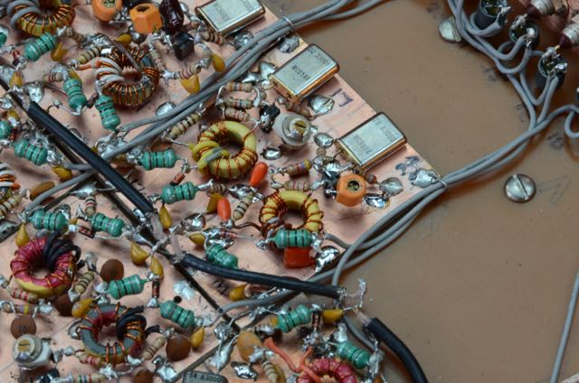
The other side contains 10 BPF's for the HFO output followed by an amplifier
chain to boost the output level to +17 dBm for the
receiver and +7 dBm for the transmitter mixer and
freq. counter. Instead of using relays to switch the xtal
osc.'s and the HFO BPF's I decided to use diode
switches. The average xtal. osc.
output level is +6 dBm and the output of the HFO
mixer is -20 dBm + or - 0.5 dBm,
thus I was not concerned about using diode switching for the osc. and BPF's like we are with the receiver RF input
BPF's where signal level can be significantly larger causing 3rd order
intermodulation distortion in the diodes. After testing various diodes I
decided that the IN4148 small signal switching diodes met my requirement.
They are two diodes switches on either side of the BPF's and forward biased
at 12 mA's per diode or 48 mA's in totl.
TOP SECTION OF THE HFO MODULE
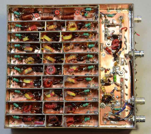
CLOSE UP VIEW OF HFO AMPLIFIER CHAIN
The HFO output power measures +17 dBm + or - 0.4 dBm for all bands 160 to 6 meters.
CLOSE UP VIEW OF TRANMITTER BOX
CLOSE UP VIEW OF HFO TR SWITCH CIRCUIT
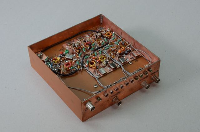
CLOSE UP VIEW OF INSIDE OF THE HBR-2018 BEFORE THE XMTR BOX WAS INSTALLED
Quick Links
1. Receiver Measurements
2. Design Process
3. IF-Detector Module
4. Audio Module
5. VFO and Frequency Control
6. RF Filters
7. Front End, Mixer, Post Mixer Amp and Noise Blanker
Gate
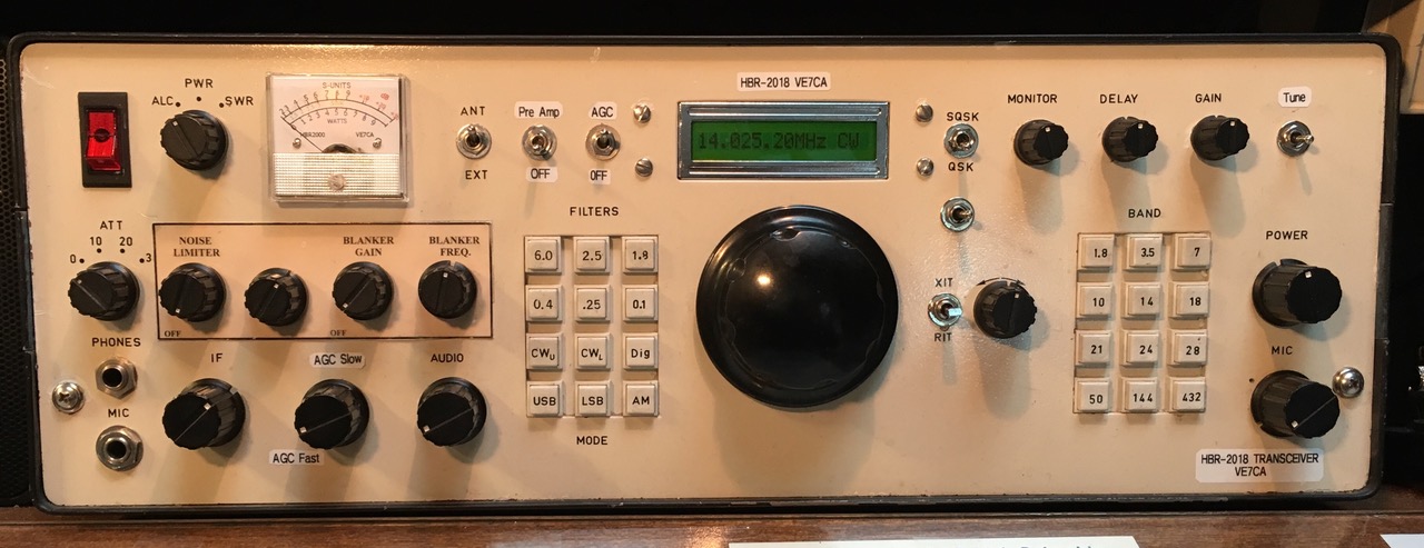
8. Front Panel Layout
9. Transmitter 100 Watt Amp.
10. Test Equipment
11. Keeping Records
Published Articles (Copyright ARRL. All rights
reserved, used with permission of the ARRL.)
...
73 VE7CA
|