|
Collins 51J-4 Deluxe General Coverage Receiver.
Page Update
February 16, 2014, Collins 51j series PTO
rebuild.
When I was a young man, I worked as a commercial radio operator at Alert
N.W.T. located on the northern tip of Canada's most northerly Island called
Ellesmere. In the radio room there were three Collins 51j-4 receivers which
were used on a daily basis. I learned to appreciate these fine quality tube
radios and I always wanted one for my home shack.
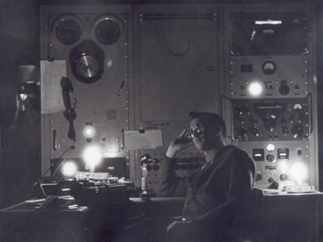
Here I am at the operating position at Alert taken while on shift in 1964.
Note the 51j-4's and Hammarlund SP-210LX. There was also a fully equipped
Collins-S line with the big Collins linear at Alert. We used the call sign,
VE8ML and I was very active chasing DX while there. Until 1999 Alert was
located in the North West Territories with the prefix VE8. When the boarders
between Canada's northern territories were re-aligned a new territory was
formed called Nunavut. It has it's own distinct prefix now, VY0.
In October 2012 I acquired a 51j-4 that was in good shape that had previously
been used in Collins Laboratory.
I really enjoy turning the big Collins 51j-4 switch to the ON position and
waiting in anticipation for the tubes to warm up. Reminiscent of days long
ago leading up to when I received my ham radio licence
a friend and I would listen to his father's table top short wave receiver to
voices from far away lands. Radio New Zealand, Cuba, China, Japan and others
are often heard on the Short Wave bands. I often tune to W1AW at 5 PM local
time to listen to the ARRL bulletins then check WWB and WWBH or CHU for the
time signals.
Much to my delight the 51j-4 is now situated next to a restored Viking Ranger
transmitter and I often use them together to make both CW and AM contacts.
When the receiver arrived it didn't take me long to begin the process of
cleaning it up.
I found on the WEB, "The Hollow State Newsletter #26" authored by
Dallas Lankford that provides helpful information about changing the existing
51j-4 BFO circuit to a combined BFO/product detector as well as improvements
to the AGC circuit.
The Dallas Lankford papers #26-37. BFO and Product Detector.
These modifications entail removing the front panel, rewiring and running
cables to the switches on the front panel
This is a photo of the BFO circuit after I modified it to a combined
BFO/Product Detector.
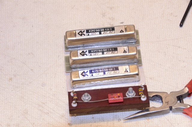
When I purchased the receiver it came without mechanical filters as it had
originally been used in one of Collins factories as a lab instrument (hence
the light grey front panel colour). The original
500 KHz Collins mechanical filters are sometimes available on the WEB but
tend to be very expensive. I found a surplus electronic dealer on eBay
located in Slovenia that sold Russian manufactured 500 KHz mechanical
filters. He sent me the specifications for the filters so I ordered the 6.0
3.0 and 0.5 KHz BW filters at very reasonable prices. The item between the
pliers is an orginal Collins coupling circuit that
is inserted in one of the filter slots when the receiver does not have any
mechanical filters installed.
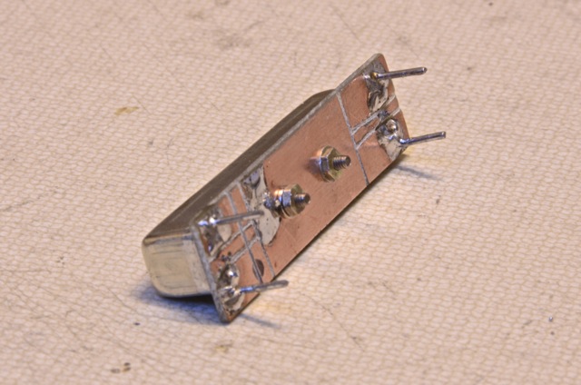
The physical dimensions of the mechanical filters are not the same as the
Collins filters so I fabricated a mounting plate from PC board for the new
filters.
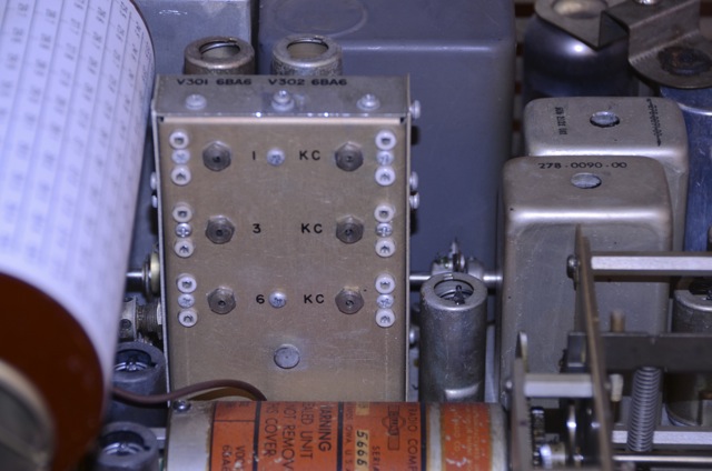
Here you can clearly see where the filters are to be installed.
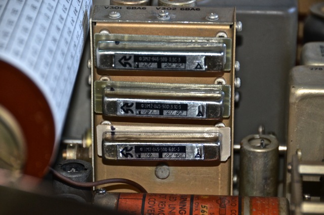
Mission accomplished. The two wider filters have a small amount of ripple. I
decided not to match them to the existing circuit as I found when listening
to SSB or AM signals that I am unable to notice any ripple.
Update February 16, 2014, Collins 51j series PTO, Model 70E-15,
rebuild.
After owning the receiver for 9 months I noticed that the receiver frequency
began wandering up and down, sometimes as much as 100 to 150 Hz and then
usually it would drift back to the original frequency I was listening to. I
decided to find out why. Checking with a frequency counter I measured both
the BFO and Xtal hetrodyne
xtals and found them stable. When I connected a
counter to the PTO (permantaly tuned oscillator) I
noticed that it was not stable which was obviously the problem that caused
the receiver frequency to wander.
The Collins model 70E-15 PTO is common to the 51j series and R-388A military
receivers. Removing the PTO from the 51j-4 is a major undertaking. The PTO
removal procedure is outlined in Section 5.4 in the 51j-4 manual. Here are a
few points that are not mentioned in the manual:
1. Remove the PTO tubes and shields.
2. After removing the front Panel, see Sec.5.6.2, and the KHz Dial, remove
the 3 spacers that are located between the PTO and the gear mounting plate.
This is not easy but once they are loosened they can be unscrewed from the
PTO with your fingers.
3. You can turn the PTO while tilting it towards the back to remove it.
4. Note it is not necessary to remove the PTO couplers.
5. I tuned the receiver to 20.0 Mhz before removing
the PTO and then measured the PTO output frequency at 2.5Mhz. When
re-installing the PTO remember to tune it to 2.5MHZ otherwise your dial can
be way off frequency and there is no way to correct it without removing the
PTO again.
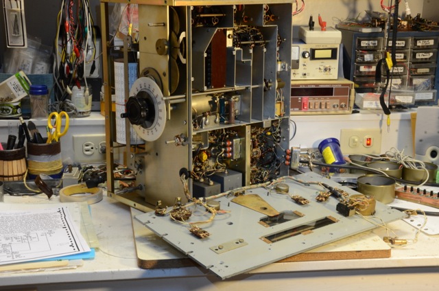
The following photo is the PTO after removal.
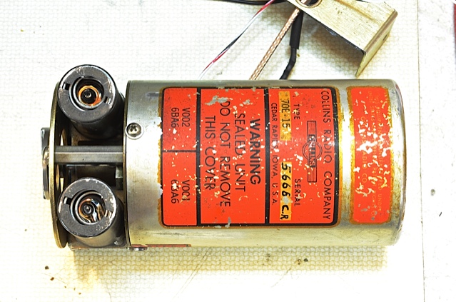
Following suggestions I found on the WEB, I replaced the two bypass
capacitors C005 and C005 as well as C008, the capacitor between the main
inductor tap and V002 screen (specified as a 0.01 UF or 1000 pF). After
applying filament and DC voltage to the PTO and letting it warm up the PTO
continued to wander.
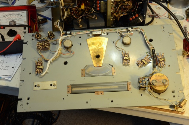
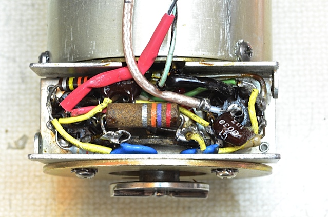
Next I decided to replace C004, C007 and all the resistors located under the
tube sockets. I made a hand drawn picture of the location of each part and
where the capacitor and resistor leads were soldered in place. The components
are tightly packed so work slowly and carefully as you remove and replace the
components. Here is a photo with the components removed.

After replacing all the components under the PTO tube sockets, I fired it up
and it did not oscillate. I checked all the tube voltages and they were
correct. Then I removed the capacitors one by one and checked the values with
a capacitor checker and they were all OK. Not knowing what to do next I
decided to try another type of capacitor for C008. For the first replacement
I used a 0.01 Polystyrene capacitor. I found a new 820 pF Silver Mica
capacitor and soldered it in place. To my surprise the PTO oscillated? I
checked the capacitor I removed and it measured OK so maybe the polystyrene
capacitor had too high an internal resistance?
After letting the PTO warm up for an hour I went back to make a chart of the
PTO drift. NO oscillation. OH NO. Further checking with a VOM I found that there
was no DC supply voltage on the V001 plate. There is a 27K dropping resistor
from DC supply to the plate of V001 and the VOM indicated that the 27 K
resistor was open. I could not believe it. It is buried underneath other
components and very difficult to get to. I was able to snip the one lead off
and insert another 27K another resistor on top and leave enough room for the
cover.
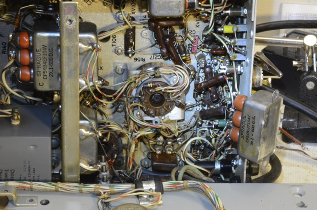
Here is a photo of the PTO after insertion of all new parts with the 27K
located on top.
I was glad to see that it oscillated but after only a few minutes I noticed
that the PTO would make an abrupt jump in frequency. It turned out the main
HV rectifier a 5V4, must have been in the process of breaking down as the HV
would drop dramatically and then rise to the proper voltage. I didn't have
any 5V4's on hand but several 5U4's so I used one of them and that fixed the
problem. Success?
After letting the PTO warm up and stabilize I made a graph of the frequency
stability. I noted the frequency every 15 seconds over a period of 10 minutes
and it only drifts plus or minus 3.5 Hz. After installing the PTO back into
the receiver and letting it warm up over night I can set the receiver to WWV
at 20 MHz with a beat frequency of 650 Hz and returning to check the
frequency several times in a day I can not notice that the frequency varies
from a audio generator tone of 650 Hz. Amazing technology for a receiver that
is nearly 70 years old.
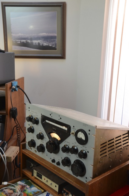
Here is a photo of the 51j-4 after a thorough cleaning, re-alignment and the
product detector and mechanical filters are installed. What a beautiful
receiver.
|