|
160 Meters
PAGE UPDATES
2013 Jan 14: Updated
information regarding my new 160 transmitting antenna.
2009 Dec 14: The ARC-4 and MFJ-1026 Noise Canceller Comparisons
2009 Dec 11: 160 Meter Contests.
1. 160 Meter Contests
I operated in both the Fall 2012 ARRL and
Stew Perry 160 Meter contests with my new Inverted L Antenna. With the new
antenna I was able to hold a CQ frequency for lengthy periods and many
stations called me. This has never happened before. Also in S&P mode,
most often I was heard on my first call even when the calling station was right
at my receiver noise level. In addition I worked the following prefixes: PJ2,
C6, XE, KH6, KH8, KL7 and JA's. I even had a JA call me when I was calling
CQ. This never happened before. I called CE/K7CA several times and he came
back with VE7? but he was unable to get the rest of my call.
In addition, several times I heard local hams who run high power (approx. +12
db advantage to my 100 watts) call someone and make a contact. I would call
as well and every time I was also able to make the contact. My conclusion is
that my new 160 meter antenna is working very well.
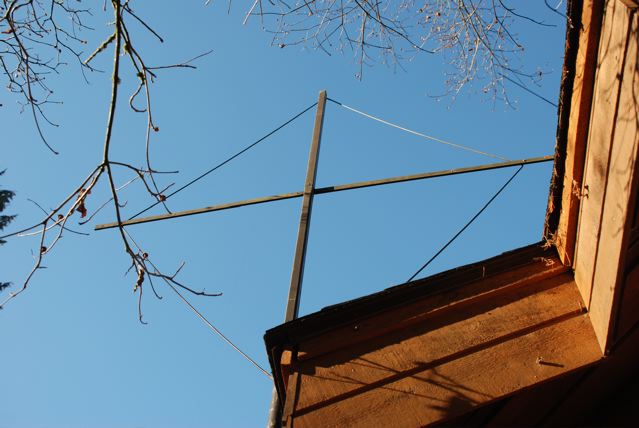
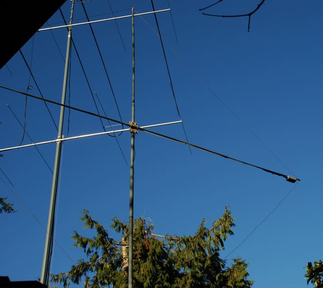
2. New 160 Meter Transmitting Antenna
I have always enjoyed operating on 160
meters. I built my first homebrew 160 meter transmitter in 1959 with parts
from a discarded TV set. It incorporated a pair of 807's in the final putting
out 100 watts. Over the last 28 years I have tried many different 160 meter
antennas. My most recent antenna for top band was an odd shaped 160 meter
full wave length loop. In October 2012 I changed my 160 meter transmitting
antenna to an Inverted L with FCP (folded counter poise). The FCP was developed
by K2AV.
I have very little space to lay radials on our city sized lot. Since a
vertical (Inverted L) is really a end-fed antenna it requires some form of
path for the return current which typically is either an elevated or buried
radial system. A properly constructed FCP can also serve this purpose within
a total length of only 66 feet. Using radials one needs a radius of
approximatley 100 feet and thousands of feet of wire which is not an option
at my QTH. I built my FCP over one end of our home at 15 feet above the
ground. The vertical wire is 61 feet and then horizontal for 64 feetwith
another 51 feet of wire sloping down at 40 degrees from the end of the 64
foot length of wire for a total wire length of 176 ft. I am fortunate to have
two 90 foot trees on opposite ends of our city size lot to support wire
antennas.
I choose to make the antenna more than a ¼ wave length in order to put the
maximum radiating current near the top of the vertical wire so that maximum
radiation is above all the surrounding houses, trees, power line poles etc.
The K2AV FCP is electrically shorter than a ¼ wave length so it requires a
series inductance to resonate. The recommended K2AV isolation transformer has
leakage inductance of approximatley 17 uH. Modeling the FCP and Inverted L
element total wire length of 176 ft. I determined that 300 Pf in series with
the radiating element would resonate the antenna near 1825 to provide a good
match to 50 ohms for my transmitter. The specifically recommended designed
isolation transformer keeps common mode current from radiating from the coax
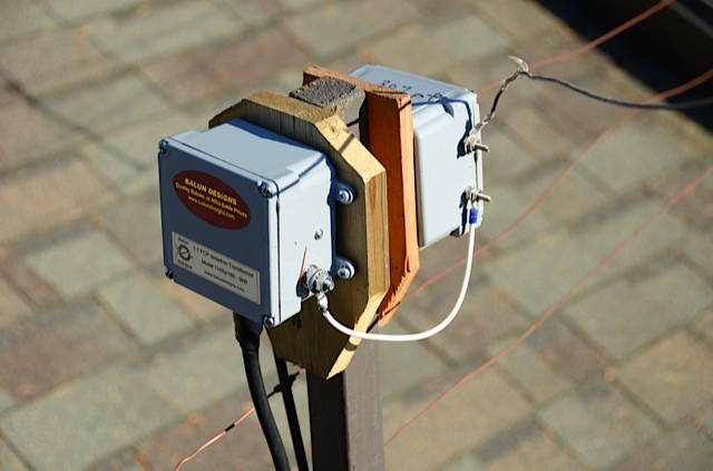
feed line. I purhased the insolation transformer from Balun Designs, Model
1142s as recommended by K2AV. I measured the 2:1 SWR BW to be 52 KHz and the
resonate frequence is 1830, PERFECT and very close to what EZNEC predicts.
Here
is a picture of the LCP isolation transformer and the box containing the 500
PF series capacitor.
For further design
information regarding K2AV's FCP, the isolation transfomer please go to: www.w0uce.net/K2AVantenna.html
With my antenna tuner I can tune the inverted L for an
acceptable SWR on all bands 80 meters to 30 meters though the radiation angle
would be very high. Good for local contacts.
If you have EZNEC you can download an EZ file of VE7CA's 160 Meter Inverted
L/FCP transmitting antenna here. Click Here
3. Noise: When I was a
teenager, my parents lived on a 5 acre hobby farm and man made noise was not
a problem. Times have changed. I now live in a city surrounded by power lines
and houses containing great assortments of electric devises. Noise is a
constant issue on 160 meters at my QTH. It is the combination of man made
noise coming from multiple sources within the city that cover the weak
signals that I want to hear.
In the evening my typical noise level on my 160 Meter transmitting antenna
varies from S5 to S6 until all my neighbours go to bed when the noise level
sometimes decreases to S4 to S5. (Receiver pre-amp off, BW 2.5 KHz, receiver
sensitivity -135 dBm).
-Solution No 1: Many years ago I tried to alleviate the noise
situation by building a small table mounted multi-turn coaxial loop which has
been featured in the ARRL Antenna Handbook for years. The signal to noise
ratio of the coaxial loop showed a small improvement compared to my
transmitting antenna but the ability to null local noise sources proved to be
unsatisfactory. It didn't help that the coaxial loop was in my radio shack
which is near the multiple AC wires in the walls that carrying RFI from many
sources in the house., i.e. TV horizontal oscillator harmonics,
microprocessors in various equipment, computers etc. A better solution to my
noise situation had to be found.
-Solution No 2: My next step was to move the listening antenna
outside. I built a one turn coaxial loop. It is larger than the table model
thus a broader frequency response and does not need to be tuned every 20 KHz.
I mounted the new loop on a 10 foot pipe with an attached rotator so I can
turn the antenna from inside my radio shack. The outside coaxial loop showed
a small improvement being it is located farther away from the household noise
sources however like the table mounted loop, the nulls were not as deep as I
had hoped for. Experimenting further, I found that when listening on my
coaxial loop, if I grounded the transmitting antenna the noise level
decreased about approximately 6 dB.
If you place a small antenna with a small capture area near a large antenna
with a big capture area (both resonant on the same frequency), the
circulating RF current in the small antenna will be overpowered by the RF
current circulating in the large antenna by mutual coupling (which in my case
contains significant man made noise). I now short the transmitting antenna
feed-line to ground with a reed relay using the TR circuit in my transceiver.
Shorting a near by transmitting antenna to ground may not work for every
situation. You may have to decouple a near by transmitting antenna (HF Tower)
by hanging a 1/4 length wire along side! When I decoupled my transmitting
antenna by grounding the feed line to ground, the coaxial loop showed a significant
null in the loop pattern when turning the coaxial loop to an offending noise
source. This is evidence that my near by resonant transmitting antenna was
destroying the coaxial loops radiation pattern by mutual coupling.
Here
is a picture of the single turn coaxial loop.
Though the signal to noise
ratio of the coaxial loop is sometimes better than the transmitting antenna
it has one flaw. It has two nulls 180 degrees apart. Also the radiation
pattern of the coaxial loop does not show any directivity other than the two
nulls 180 degrees opposite to each other. Turning the coaxial loop to reduce
a noise source towards the West, sometimes nulled a signal I want to hear to
the East.(depending on the arrival angle of incoming signal). I found that
often when I would null a noise problem I also reduced the signal level of a
station I was trying to copy.
-Solution No. 3: A popular low noise receiving antenna used by Low
Band operators is the EWE, Flag and K9AY antennas. These antennas are
physically small in terms of wavelength and composed of phased verticals or a
terminated loop. (type in EWE, Flag or K9AY in your search engine and you
will find numerous sites devoted to these antennas.) Properly constructed
these antennas are omni-directional and have only one null.
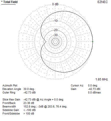
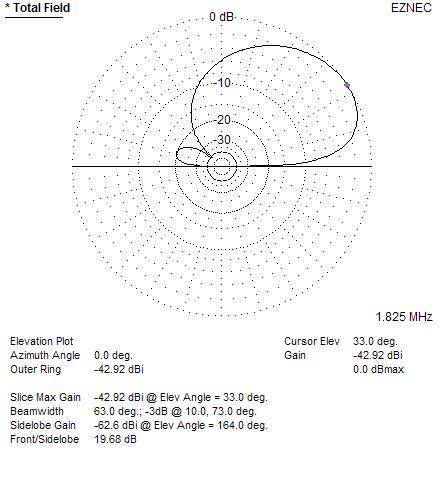
Using EZNEC I designed a small diamond shaped terminated loop. It is mounted
on a 12 foot pipe and rotated with a spare rotator. The diamond loop is
supported by fibreglass poles extending 7 feet from the centre hub thus it
has a turning radius of only 7 feet.
Following are
the Horizontal and Vertical plots for the Diamond Terminated loop.
If you have EZNEC you can download an EZ file of VE7CA's Low Noise Terminated
Loop Click Here
4. Outdoor Terminated Loop Antenna
With the side opposite the feed-point
terminated in a 860 ohm resistor, the antenna shows a steep -35 dB when the
back is turned to a local broadcast station at 1750 KHz. Because the loop is
physically small compared to a full sized 160 meter antenna great care must
be taken to decouple the feed-line from the antenna in the balanced versions
of these antennas. Generally the antenna looks capacitive as a common-mode
structure, so inductive decoupling (i.e. a choke coil of coax) can actually
increase the system problem. The best common-mode isolation system is an
isolated winding transformer designed with minimal capacitance between the
antenna winding and the rest of the system. Also, increasing the signal level
at the feed-point, decoupling beads on the feed line and grounding the shield
of the coax close to the receiver input all play an important role in
reducing common-mode problems.
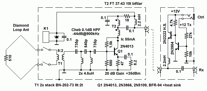
Following is the circuit of a wide band pre-amplifier that I built (taken
directly from EMRFD.) It is located at the feed-point and enclosed in a
plastic weather proof box. The amplifier has a gain of +21dB at 1.8 MHz,
+18dB at 7 MHz and zero gain at 60 MHz. A high-pass filter is located between
the relay and the amplifier input to attenuate local broadcast stations. OIP3
is +35 dBm, the noise figure is estimated to be approximately 3-4 dB and the
amplifier draws 55 mA’s. I included a relay (operated by the TR circuit in my
transmitter) that opens up the terminated loop on transmit. This reduces the
risk of burning out the pre-amplifier by induced high levels of RF from my
nearby transmitting antenna. T1 is two stacked BN-202-73 Amidon cores with 8
T primary and 2 T secondary. T2 is a FT-37-43, 10 turns bifilar. Power for
the pre-amplifier and the relay is via the centre conductor of the coax
feed-line. This antenna is also effective as a receive antenna in the
Broadcast band so if you are interested in using it for Broadcast listening,
leave out the high pass filter. Depending upon your own particular situation,
if there are AM Broadcast stations near by, you may still need a broadcast
band filter that you can switch in when using the antenna for 160 or 80
meters.
Pre-amplifier
Circuit.
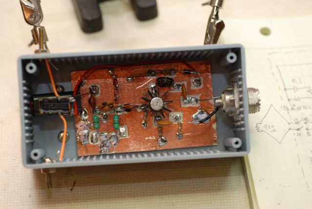
Pre-amplifier mounted and remote control head.
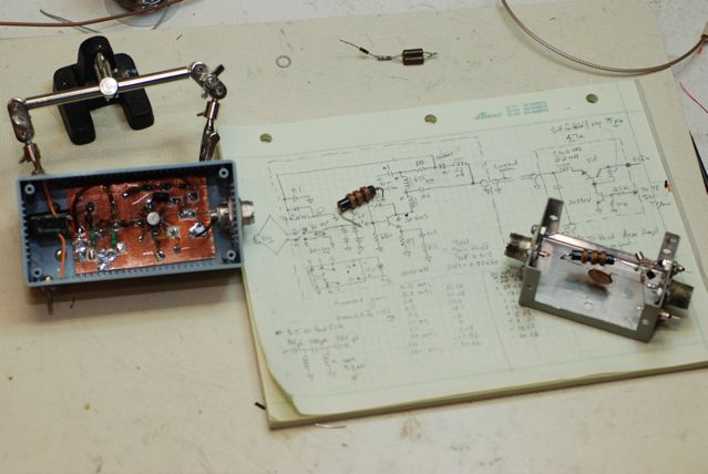
Pre-amplifier mounted in the remote plastic box.
Important: The terminated
diamond loop is a balanced antenna and I am feeding it with an unbalanced
coaxial feed line. It is of utmost importance to decouple the coax shield
wire from the antenna! The shield must act only as a shield and not as an
antenna allowing pick up of noise along the feed-line otherwise the radiation
pattern of the terminated loop will be compromised. This is called
common-mode pick up and is very undesirable. To RF decouple the shield of the
coax feedline I placed 12 ferrite beads, Mix 77, over the RG58u coax
feed-line next to the remote pre-amplifier box. This is often referred to as
a current balun. Palomar Engineers sells kits for this purpose and two sets,
Model BA-58, are required for 1.8 MHz. www.Palomar-Engineers.com
Pre-amplifier
mounted at the end of one of the fiberglass arms; note location of current
balun.
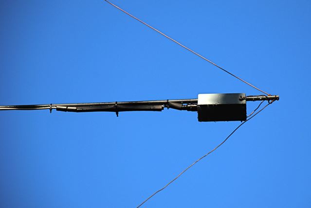
Here is the terminated diamond loop with the VE7CA yagi's in the background.
In order to determine if one antenna is better than
another I built a relay operated antenna switch so I can switch between
receive antennas without having to fiddle with coax connetors. I mounted 4
relays in a Hammond aluminum box with 4 BNC connectors for the receive
antennas and another BNC connector for the output. I used decoupling feed
thru capacitors for the control wires which run to a rotary switch on my
operating desk.
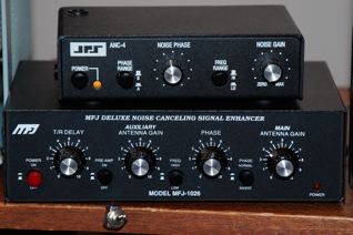
5. Noise Canceller:
Every 160 meter enthusiast should consider adding a noise canceller to their
list of ham radio equipment. A noise canceller is a device that allows
adjustment of the phase and magnitude of an offending noise source so that it
is 180 degrees out of phase with the signal you want to hear thus reducing
the level of the offending signal, (noise or another station). I purchased an
ANC-4 Noise Canceller many years ago and have found it a worth while addition
to my ham shack. It is now being sold by Timewave. MFJ also sells a noise
canceller, model number MFJ-1026. See the next section for my comparison of
the two units.
A noise canceller can only null noise arriving from one direction. If you
have noise arriving from multiple sources arriving from different directions
then a noise canceller will not be of much help. In my case, my low noise
Terminated Diamond Loop has a deep null which I can turn to an offending
signal and the noise canceller can be adjusted to null noise or signals from
another direction. It is important to keep in mind that the most effective
noise reduction system is to find and then remove the offending noise.
Previously I had successfully used the ANC-4 on all HF bands from 40 to 10
meters but not on 80 and 160 meters. The ANC-4 has a “noise antenna gain”
adjustment but it does not have enough gain on 160 and 80 meters to boost the
noise from my noise antenna sufficiently (my noise antenna is short for 80
and 160 meters) to be equal to the noise from my transmitting antenna. In
order for a noise canceller to work, the level from the listening antenna and
the level from the noise antenna must be near equal in strength. The overall
signal level from the low noise Terminated Diamond Loop is very close to the signal
level arriving from my noise antenna and now the ANC-4 works very well on the
lower HF bands..
Expect to try many different noise antennas before you find one that works
for your installation. My noise antenna is a 40 to 10 meter multi-element
wire-dipole located in the West end of the attic of my home. The Terminated
Diamond Loop is at the opposite the end of the house. I have found that I
need approximately 1/8 to 1/4 wave length separation between the listening
and noise antennas while using a noise canceller otherwise tuning becomes
very touchy or even impossible to adjust for effective noise reduction.
6. Results: The
terminated loop in conjunction with the ANC-4 noise canceller has improved my
ability to copy many more stations on 80 and particularly 160 meters. I have
heard a FM5, XE2, P40, LU3, JA and a CE1 station which with the low
terminated lopp which were not copialbe with my transmitting antenna.
Comparing the coaxial loop to the terminated loop, if the noise is not in
line with the station I am trying to copy, then the two antennas are nearly
equal.
During the evening of September the 25th, 2009 West coast stations were
working European stations every few KHz's on the bottom end of 160 meters.
Since W7's and VE7's were giving 599 reports I decided to see if I could hear
any of the European stations with my 160 meter low noise Diamond Terminated
Loop antenna described below. Turning the terminated loop towards Europe and
using my ANC-4 noise canceller I was able to reduce the noise level to near
zero on my S meter. Receiving with my transmitting antenna the noise was S-9.
Tuning across the band I was amazed to hear SM5EDX loud and clear though
weak, about S-2. Later I heard OH3HR. I tried to work them both but my 100
watts didn't make it. My QTH is located on the southern slope of Grouse
Mountain (elevation 1,231 m {4,039 ft}). Because of the upward slope to the
north, my antenna is looking into the houses two blocks above my home so I
think you can imagine the difficult position I am faced with trying to work
Europe on 160 meters. This was the first time I have been able to hear
European stations on 160 meters from my QTH so if I can hear them, I know
that I will eventually work them.
There are situations where the terminated loop is better than the coaxial
loop, especially when listening to DX stations. My conclusion is the
terminated loop is a worthy addition to my amateur radio enjoyment.
7. Noise Canceller Comparisons:
There are many opinions about the
effectiveness of the ANC-4 and the MFJ-1026 noise cancellers. Since I have
both, I decided to make side-by-side comparisons measuring and listening to
real interference. Because interfering signals typically are not static, i.e.
their signal strength varies over time (QSB) one has to be able to switch
very quickly between the two units to determine if one is better than the
other. Removing the coax antenna connectors from one unit and moving them to
the other is not quick enough. So, I built a simple relay switching system
that allows, with the flip of a toggle switch, quick selection of either the
ARC-4 or the MFJ-1026.
|
ARC-4 and
MFJ-1650
|
Switching
System
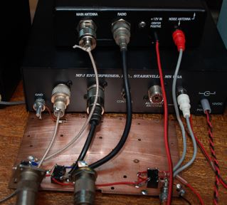
|
My observations after switching between the two cancellers, many times over a
period of several months while listening to different types of interference,
(steady carries, wobbly computer birdies, noise etc) is that both cancellers
are essentially equal in their ability to null interfering signals. I
measured the difference three different ways.
-1. With the AGC enabled I observe the S meter difference between the
interfering signal and when it is nulled. Since the ANC-4 antenna input gain
is fixed and the MFJ-1650 is variable I note the S meter reading on the ANC-4
and then match the MFJ-1650 to the same level. I then adjust both cancelers
for the best null. Then switching between the two units I am able to observe
the difference in the null depth.
-2. The second method I measure the difference in the nulling ability with
the AGC turned OFF while observing the level on my scope. With this method, I
am able to measure the difference in level between the received interfering
signal to the signal when it is nulled. This elliminates the need to adjust
the antenna gain of the MJF-1026 to match that of the ANC-4.
-3. The third method is to listen to interfering signals on my receiver and
see if I can hear any difference between the two units when they are adjusted
for maximum interference rejection.
Employing all three methods, I have not been able to descern that one
canceller is significanlty better than the other in their ability to reduce
offending signals. With the right combinations of antennas, patience and
knowlege very deep nulls (in excess of 55dB) can be realized with either
canceller. The ability to switch quickly between the two units enabled me to
make realistic comparisons between the two units.
It is worth mentioning that the ANC-4 is much easier to tune for a null than
the MFJ-1026. As previously mentioned, one has to first adjust the antenna
gain of the MFJ-1026 before you can hear any signals, then tweak the noise
antenna gain and phase and antenna gain controls for the best null. These
adjustments are very critical which I found quite frustrating. With the ANC-4
you simply increase the noise gain while you adjust the noise phase knob for
a null. Once I find a null, I then just adjust the noise gain for optimum
noise cancelation.
All the above experiments have been carried out on the lower HF bands with my
particular noise antenna in combination with the Low Noise Terminated loop. I
must stress that every installation is different from another and there are
many many variables between installations. You may obtain different results
using your particular antennas. There have been instances where I can obtain
a good null with the ANC-4 and not the MFJ-1026 and vis-versa for which I
have no explaination.
Here is a copy of an email from Tadek, SP7HT regarding his experience with
the ANC-4/MFJ-1026 plus information regarding modifications he made to his
ANC-4.
"For years I am competing
with local noises using ANC-4 (firstly) and MFJ-1026 (last 10 months) for
noise cancelling. I've modified the Front End of my old ANC-4 adding a tuned
resonant circuit at the Input of Noise Channel (low impedance Input to
resonant circuit, next High impedance paralell resonance circuit using
ferrite core and RX tuning capacitor I can cover in 4 sub-bands from 1.74MHz
to 30.1MHz and at the output low impedance to connect directly to ANC-4 noise
antenna Input socket).
At the Output of that modification (outside ANC-4 case) I can adjust the
level of noise signal (470 Ohm potentiometer) connected to ANC-4. So, I can
adjust NOISE GAIN in the middle position, when best cancelling can be reached
(in ANC-4).
Thanks to selective resonance circuit at the Input of Noise antenna I can
avoid intermodulation products when propagation is in a great shape (birdies
appeard every 5kHz or every 10kHz).
According to local noises in my location (a 5 floor block of flats, 19
neighbours in that house and about 300 neighbours in 100 metres circle around
my location) I can say (today) that my modified ANC-4 is an exellant tool to
fight with local noises"
Tadek's addition of a variable pot (attenuator) at the Noise Antenna input is
a good addition to the ANC-4 if you are using a noise antenna that has more
gain than your receive antenna such as a EWE, Flag, K9AY or Terminated Loop.
An attenuator at the noise antenna input provides a wider range of control of
the noise level allowing a closer match to the two antenna input levels.
|