
A little history of the Mackay Company which manufactured the HF transmitter and receiver used on the SS Red Oak Victory and many other Victory and Liberty Ships) is provided by Michael C. Beck of Thales Mackay Radio, Inc in North Carolina. This was received in response to an email inquiry from ROVARC member Larry Fitzsimons.
SF Bay Area residents generally know about the "mothball" fleet. Both the Red Oak Victory and the Jeremiah O'Brien were residents of the ready reserver. Here's an article that describes the fleet in a little more detail. S.F. Chronicle 2/7/2003
The radio equipment console that you see in the images below is fully operational and virtually all original. It was manufactured in 1944 by the Mackay Radio division of Federal Telephone and Radio as model FT-106. It is divided into three sections: Left, Center and Right.
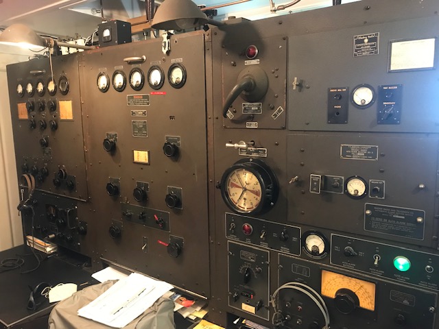
Here's a view of the Mackay console. Space in the radio room is a little tight. Be that as it may, this panorama still gives a pretty good idea of positions of the three major sections of the console described in the the following sections.
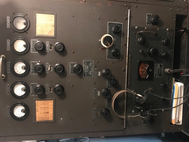
The left panel houses the short-wave transmitter (Mackay 167-AY) in the upper portion. In the lower portion is the short-wave receiver (E. F. Scott SLR-F). Short-wave operation is from 2-24 Mc. While the equipment in the original console can receive both voice and Morse code transmissions, it can only transmit in Morse.
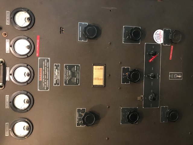
Here's a view of the center part of the console, which contains the main transmitter (Mackay 155-AY), operating from 400 to 500 kc, and the battery charger controls.
All of the equipment in the console (except for the Scott HF receiver which is AC powered) operates from 115 volt DC current. If the ship's 115 volt distribution system fails (say, due to a stray munition) the radio console can be battery powered. The radio battery room is through the doorway to the left and behind of the console. Power output for each transmitter is about 200 watts.
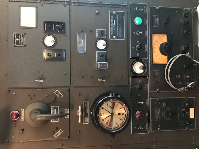
At the upper left of the right panel section are the antenna selector switch and below that the antenna grounding switch. The Mackay 101B Auto Alarm receiver and selector is to the right. You can see the radio room clock (below the antenna grounding switch) with special markings for the silent period and auto alarm attention signal. The area just below the clock and auto alarm equipment contains battery selector and charging controls for the receiver and auto alarm. The main receiver (Mackay 128-AV) is at the bottom right, covering 15 to 650kc. Below the clock and to the left of the main receiver is the emergency crystal radio (Mackay 123BX).
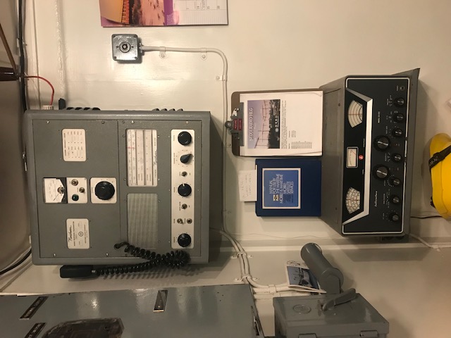
A radiotelephone transceiver is on the wall to the left of the console. It was added during the Vietnam era. Below it is an additional receiver for monitoring, also from the Vietnam era.
To the left of the radiotelephone, is the DC power supply Normal-Emergency switch.
On the floor, under the radiotelephone, (not shown) spare motor-alternator units (main and emergency) being refurbished for use in the console.
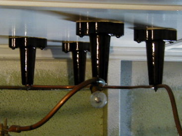
Ceramic insulators leading the antenna lines into the Mackay transmitter and receiver. The small neon bulb acted as a very analog watt meter to give a rough estimate of power output. Amazing how nice a ceramic insulator can look in the right light!
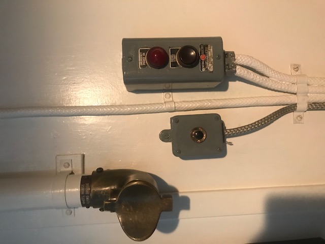
On the back wall, behind the radio operator's seats, we see the speaking tube to the wheelhouse to the left (blowing into the tube sounds a whistle in the wheelhouse to get their attention). On The right hand side is the start control for the emergency diesel generator. And, in the middle is a button that rings a bell in the galley to let them know the RO wants something to eat!