DRM
MF 455kHz -> AF Converter
RE-RXC0455/0012
(455kHz
down converter)
MFC revision 1.4
MF (455kHz) to AF
(audio frequency) Converter/Interface
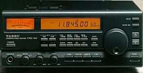
to receive DRM singals your shortwave receiver, like the Yaesu
FRG-100!
and
FT-817/897
Please take also look at our
Digital Analog
Demodulation Project
(DADP, VE7DXW)
Attention! The
modification will be done at your own risk!
About
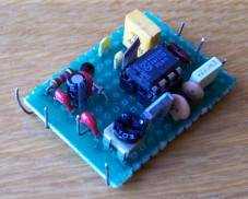
the MF-LF converter/mixer RXC455/0012:
This is a very
sensitive homemade MF converter/interface allowing you to
receive the DRM radio (Digital
Radio Mondiale) with
your general coverage receiver and a soundcard. It can also
be used for software radio apllications, and other MF to LF
experiments (not just DRM, and surely not just for the Yaesu
FRG-100)!
I've tested this project on a allmode Yaesu FRG-100 receiver.
Within certain limits you can change the output bandwidth
frequency to suit your needs. The converter is very stable,
low noise, sensitive and low on power consumption.
The heart of the converter has been built around Philips
SA602 (NE602, NE612, SA612), a twice balanced mixer
oscillator. This IC finds his applications in layer capacity
communication systems, cellular radio applications, RF data
left, VHF-transceivers, broadband LAN's ed. IC in a ordinary
8-pin dual-in-line can be bought implementation (DIP) or
8-pin SO (surface-mount miniature package) implementation.
Both implementation has a low cost. SA/NE602 a very low usage
of only 2,4mA has! The total usage of the converter amounts
to only 13mA. Therefore also uncomplicated usable
applications fed with battery if needed, but in this
converter's DRM application I use the voltage of the receiver
itself.
The SA602A is a
low-power VHF monolithic double-balanced mixer with input
amplifier, on-board oscillator, and voltage regulator. It is
intended for high performance, low power communication
systems. The guaranteed parameters of the SA602A make this
device particularly well suited for cellular radio
applications. The mixer is a “Gilbert cell”
multiplier configuration which typically provides 18dB of
gain at 45MHz. The oscillator will operate to 200MHz. It can
be configured as a crystal oscillator, a tuned tank
oscillator, or a buffer
for an external LO. For higher frequencies the LO input may
be externally driven. The noise figure at 45MHz is typically
less than 5dB. The gain, intercept performance, low-power and
noise characteristics make the SA602A a superior choice for
high-performance battery operated equipment. It is available
in an 8-lead dual in-line plastic package and an 8-lead SO
(surface-mount miniature package).
Revision 1.1(June
09)
I have added a low noise transistor (Q1) to amplify the
output to a more convenient level, as I noticed that the
audio level was just below the ideal level on one PC, whilest
on my laptop the level was enough. Remember to set the ideal
audio volume level if needed from within your OS.
R4 (already existing in rev.v1.0) and C13 gives some
additional filtering of the LF signal.
Revision 1.2(Nov
09)
I have noticed that by adding C17 hence limiting the highest
frequency responce and amplifying the lower 5...20kC gave
additional improvement.
P (trim pot) of 2k5 to allow exact LF output level setting
for your soundcard input
Voltage for Q1 now also 6 volt (tapped from IC2)
Revision
1.3b(Nov, 21th 09)
C19 & C18 added as it gave a noticable cleaner signal but
lower LF output
R7 removed to compensate lower LF output
v1.3b: C18 added
Revision 1.4(Nov 14)
Changed the extractionpoint from the FRG
Some components left out to simplify the project further
RXC0455/0012 455KHz
converter technical specifications
- Frequency range from
455kHz...467kHz
- LF/AF out 100...12kHz
- Power supply = 9...18v max
- Total power consumption =
13mA
- Power consumption IC1 = 2,5
mA
- Sensitivity = 0.22uV at
12dB SINAD
- Mixer noise figure = 4,6dB
- Input impedance = 3k
- Output impedance = 1k
- Local oscillator 467kHz
- Frequency stability = +/-
5Hz
- Operating ambient
temperature range = -40 to +85°C
RXC0455/0012
SCHEMATIC
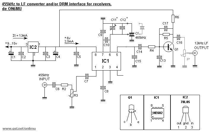
PARTS
IC1 = NE602/SA602 or
NE612/SA612 (all pin compatible)
IC2 = 78L06
Q1 = BC109,BC107
C1, C4 = 2.2uF/25v
C2, C3 = 100nF
C5 = 470pF
C6 = 100nF(polyester)
C7 = 68nF (polyester)
C8 = 100nF
C9 = 1nF
C10 = 820pF
C11= 100pF trimmer
C12 = 220pF
C13 = 1n5 (poly)
v1.1
C14 = 220nF (polyester)
C15 = 2n2 (mylar,poly)
C16 = 220nF (poly) v1.1
C17 = 120pF v1.2
Cf = 465B (ZTB465
kHz, or 470kHz) ceramic filter resonator
R1*= 10k (not specified in the schematic, see text)
R2 = 1k8
R3 = 10k
R4 = 1k
R5 = 100k (v1.1)
R6 = 2k2 (v1.1)
P* = 2k5 (v1.2)
Ceramic resonator:
Cf is a simple 465 khz ceramic filter (3 pin or 2
pin version can be used). These can sometimes be found in a
AM/FM transistor radio, old wireless telephones etc.
Ideal would be a quartz version as this offers best stability
and accurate resonating frequency of the mixer.
There are many out there that are not exactly on frequency!
When using it for DRM the mixing frequency is not critical,
so you can use a 470 kHz type too.
If the bandpass is not 12 kHz and the frequency is too high
you will need to adjust the mixing frequency Cf by using C11.
If the bandpass does not reach 12kHz because of the mixing
frequency being too low you will need to add a capacitor in
series with the ceramic resonator Cf, something between 100pF
and 300pF. I would recommend starting with 150pF (or use a
trimmer).
- ceramic filters can be
order here (only EU)
What's DRM
The Digital Radio Mondiale
(DRM) purpose is to develop a non-proprietary technical
standard for the replacement of analogue AM (Amplitude
Modulation) radio with digital radio, also called DRM.
As a replacement for AM the existing channel spacing, medium
and long wave 9 kHz and 10 kHz for short wave, is maintained.
On medium wave a DRM radio broadcast can provide close to FM
audio quality - most people will relate to the poor audio
quality of AM music. With DRM the audio quality is primarily
determined by the broadcast mode and spectrum occupancy (i.e.
radio bandwidth of the DRM signal).
It also the displays the name of the radio station, program
text, and automatic tuning to alternative frequencies will
make DRM receivers easier to operate. DRM can also transmit
multimedia html pages and data.
If you listen to a DRM signal on an ordinary short-wave AM
radio then all you will hear is noise. There is no
discernible modulation pattern when listening to DRM using a
AM demodulator.
DRM Stations recent schedule list
The (DRM) converter
explained using a Yaesu FRG-100
There are examples enough
around which use another filter by replacing the original
LF-H2S with a 12kHz or 15kHz wide filter. This allowed the
user to use DRM reception by selecting the AM-narrow mode.
The MF output is there tapped from the (hot) connection of
VR1002 as seen from the front panel to the IF input of the
converter(mixer).
In this modification I use the unused CW-filter connections
hence avoiding to remove the top board and
soldering/replacing the stock AMN filter. However, both
methodes work.
Note: In this example DRM-mode is selected by selecting CW/N
mode on your FRG-100.
Calibrating
The converter is best
calibrated to fit 12 kHz wide LF output. C11 and C12 primary
determines the offset of the base resonating frequency of the
465kHz filter. With a frequency counter you can check the
resonating frequency which should be around 467kHz. The
converter/mixer outputs 467-455=12kHz wide AF output to be
fed to your PC's soundcard input.
Set C11 to get as close as possible to 467kHz. It is possible
that C12 need to be changed to if the desired frequency isn't
reached.
I have found that it isn't too critical, although calibrating
gives the best result. However, it should work as is (set C11
to half way).
Set R3 to the best signal/noise ratio, hence also setting the
maximum output of the converter.
Note:
You can add a trim pot of +/- 2k5 at the output of Q1 after
C16 to set the ideal output for your soundcard input.
If the bandpass is not 12 kHz and the frequency is too high
you will need to adjust the mixing frequency Cf by using C11.
If the bandpass does not reach 12kHz because of the mixing
frequency being too low you will need to add a capacitor in
series with the ceramic resonator Cf, something between 100pF
and 300pF. I would recommend starting with 150pF (or use a
trimmer).
Power source voltage
The converter Vcc voltage
can be tapped from just about anywhere in the FRG-100. You
can use the 12 volt input, or tap from the 9volts running
allover the board. Tap often used is R1074 (closest to the
front to the UB connection of the mixer board) where you find
+9volt.
Any voltage from 8 to 18 volts can be fed as the converter
uses a 78L06.
Using the CW/N
optional filter connections
 red wire is the +9v
tapped from R1074, 47k resistor and ceramic filter is
connected to the CW/N filter connector to get MF
red wire is the +9v
tapped from R1074, 47k resistor and ceramic filter is
connected to the CW/N filter connector to get MF
It is perfectly possible to use the CW/N filter connections
of the FRG-100 to tap the MF 455kHz...465Khz to feed it to
our converter/mixer.
Use a 455kHz filter of 12...50kHz (often found in those old
FM transistor radios etc.). This is soldered between pin 1
(top one) of CW/N filter connector P1002 and pin 4 of P1001
(bottom pin). A 47k resistor from P1002 pin 1 is fed to the
input of the converter.
If you can not find such a ceramic filter (doubt it) you can
replace it by a few caps (this is not a drop-in
replacement, but workable enough to use for DRM with good
signals till better is found).
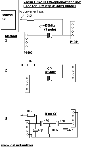
Note: DRM-mode is selected
by selecting CW/N mode.
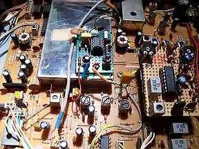
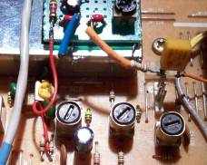
I soldered several of the converter
grounds to the VFO chassis (approx. middle of the picture)
You can see the yellow/greenish 455kHz 20kc ceramic filter
(between the converter and the FM-unit)
On the right side you can see my homemade FM-module based upon
the Yaesu schematic found in the manual.
Output/tuning/setting
The output of
the converter is fed to your soundcard using a female
connector (on the backside of the receiver). I drilled a hole
at the back of the FRG-100 to mount a 3.5mm female connector.
Use shielded wire to connect the converter to the connector.
R3 sets the maximum level of the MF signal supplied, hence
adjusting R3 can improve the signal-to-noise ratio depending
on the input sensitivity of your soundcard and/or do to the
MF voltage input. Set R3 to 80% to start with. Adjust the
adjustment on the mixer board for a DRM-signal of
approximately 50mV RMS.
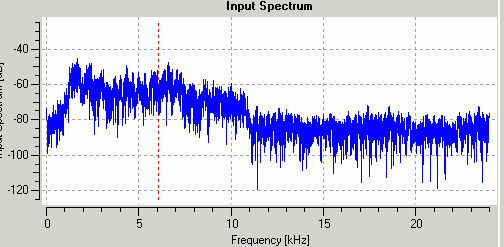
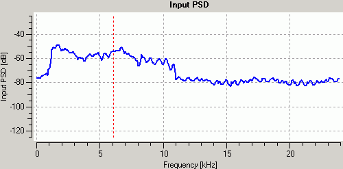
This is how a
typical DRM signal looks like:
- Connect the
decoder software to the 12 kHz IF output of the converter.
- Set the input volume of your PC properly.
- Set your FRG-100 to CW/N mode.
- Tune to a good DRM signal (3995,5955,6095,13810Khz...).
...Note: I have found that by
tuning +/- 2Kc of the DRM signal, the quality improves.
Possible reason could be the sound card timing accuracy, or
the LO frequency is not exact. Experiment!
...Note: To decode a DRM signal,
the signal strength needs to be high and the S/N ratio has to
be at least above 12dB
- Once you here the software decoding the DRM-signal you can
further tweak the settings as explained above. And, the
software itself has several settings that can improve the
reception/decoding capabilities.
Some
examples of decoded DRM signals using this converter/mixer and a
Yaesu FRG100
Software
DRM
Dream
http://drm.sourceforge.net
Dream - to decode DRM signals: Dream v1.16 compiled version
...The necessary Qt runtime library
"qt-mt230nc.dll" can be downloaded at:
...http://prdownloads.sourceforge.net/netclipboard/qt-mt230nc.dll?download
...Optional download: AMSchedule.ini
...Get the current shortwave
broadcasting schedule for AM stations from:
...http://drm.sourceforge.net/download/AMSchedule.zip
Other DRM software: http://home.arcor.de/carsten.knuetter/drm.htm
SoDiRa
..Free Software Radio (also good for
DRM)
..Tip: choose in
Config->Receiver->Type: DSR30
..http://www.dsp4swls.de/sodira/sodiraeng.html
WinRadio
..Commercial DRM Demodulator/Decoder
for Windows 2000, XP and Vista
..Tip: Choose general-purpose DRM
Software Radio (DRM demodulator/decoder for third-party
receivers)
..http://www.winradio.com/home/download-drm-2.htm
SDR
HMDSR
HMDSR is a powerful and free SDR capabale
package.
Hhomepage
HHDSDR
Homepage:
..HDSDR is a freeware Software Defined Radio
(SDR) program for Microsoft Windows 2000/XP/Vista/7/8.
..download
..Typical
applications are Radio listening, Ham Radio, SWL, Radio
Astronomy, NDB-hunting and Spectrum analysis.
..HDSDR (former
WinradHD) is an advanced version of Winrad, written by
Alberto di Bene (I2PHD).
..SDRadio:
..SSB, CW and AM demodulator: http://www.sdradio.eu/sdradio/
..By I2PHD and IK2CZL, practic
skin, made for für I/Q direct mixing concepts,
..demodulates also by set an offset
of middle frequency
..to 12 kHz single IF very well.
Can handle 40kHz+
..G8JCFSDR:
..Software defined radio using MF: http://www.g8jcf.dyndns.org/g8jcfsdr/
..By G8JCF, good AM, better SSB and
CW demodulator, also software AGC.
..Several filter and noise
reduction equipment. Also recorder mode supported.
..http://www.g8jcf.dyndns.org/g8jcfsdr/
..SM6LKM:
..A Soundcard Based SAQ VLF Receiver:
..http://web.telia.com/~u33233109/saqrx/saqrx.html
..SoDiRa
..Free Software Radio (also good for
DRM)
..http://www.dsp4swls.de/sodira/sodiraeng.html
..SDRadio
..I2PHD's SDRadio can be downloaded
from here:
..http://www.sdradio.org/
..IFDSP
..IK2CZL's IFDSP can be
downloaded from here:
..http://www.detomasi.it/en/project.html
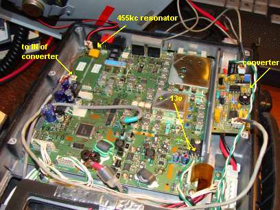
DRM
reception with the Yaesu FT-817
We use the
optional CW or SSB Filter slot in the main unit. You must
have this slot free (no optional filter) for using DRM on
this radio.
The 455 KHz Signal for the DRM mixer can be easy taken from
the first pin (from right) of J21 connector and connect the
ground of cable to the second pin.
Now put a 455kc resonator between the first right pin of J20
and the first right pin of J21. Note: You can use simular
like used in the FRG-100 please see fig2.
If you do not have a 455kc resonator then a capacitor of +/-
120 pf will be do, but you loose the agc advantages.
Switch on the rig and enter in the Menu System (press and
hold the [F] key for on second) and choose Menu Item 38 [OP
FILTER] setting mode CW.
You can activate now the DRM reception using the function NAR
of the operation menu and setting CW MODE.
DRM
reception with the Yaesu FT-897
Look for the
slots for optional CW or SSB filter (backside, left)
It’s labelled: J24 and J23.
Bridge the left two pins of J24 – so the software will
use this slot as if the SSB filter is installed.
Put a 455kc resonator between the right pin of J24 and the
right pin of J23. The third pin of J23 is connected to
ground.
If you do not have a 455kc resonator then a capacitor of +/-
120 pf will be do, but you loose the agc advantages
Connect the DRM converter to the two right pins of J23
(ground and 455 kHz IF in).
I tapped 13 volts from the 8 volt voltage regulator (see on
photo lower right corner). This connection is in consistency
with the power on/off state of the rig.
For using the converter you have to enable the 2.3 kHz
optional Filter setting in Menu (that’s the reason for
the J24 jumper)
drm using a FT-897
Tips
* This converter can also be
used to feed a LF-amplifier (listen to signals unfiltered)
* Works with some software defined radio (SDR) programs, like
SDRadio from I2PHD!
* Use it to analyse wide band spectrum
* Modify the converter to allow even wider bandwidth by
changing the resonating ceramic filter.
* Can of course be used by any receiver that has a 455kHz MF
you can tap.
More about the SA602
(NE602,SA612,NE612,SA162) in this project
The SA602A is a Gilbert
cell, an oscillator/buffer, and a temperature compensated
bias network as shown in the equivalent circuit. The Gilbert
cell is a differential amplifier (Pins 1 and 2) which drives
a balanced switching cell. The differential input stage
provides gain and determines the noise figure and signal
handling performance of the system.
The SA602A is designed for optimum low power performance.
When used with the SA604 as a 45MHz cellular radio second IF
and demodulator, the SA602A is capable of receiving -119dBm
signals with a 12dB S/N ratio. Third-order intercept is
typically -13dBm (that is approximately +5dBm output
intercept because of the RF gain).
Besides excellent low power performance well into VHF, the
SA602A is designed to be flexible. The input, RF mixer output
and oscillator ports can support a variety of configurations
provided the designer understands certain constraints, which
are explained here.
50Mc converter de ON6MU
SDRadio
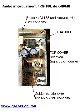
FRG-100 audio improvement
Dream v1.16 compiled version
Example of a decoded DRM signal
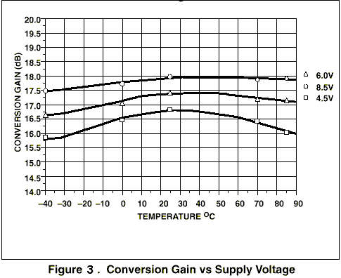
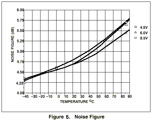
Technical graphs:
Please also look at
our Digital Analog
Demodulation Project
(DADP, VE7DXW) that explains in high detail how to use it for the
Yaesu FT-817 and simular transceivers
More about these
mods:
50Mc converter de ON6MU
SDRadio
FRG-100 audio improvement
Dream v1.16 compiled version
Example of a decoded DRM signal
Ham mods modifications
Youtube:
This is how Tonino IZ6QTX made it and how he is using it:
http://www.youtube.com/watch?v=VoKhKgP2duM
http://www.youtube.com/watch?v=5MvFH9X5kpU
Thank you Tonino!
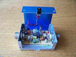
Please take a look at my 50MHz converter which
is ALSO based on the SA/NE 602 mixer!
50 MHz converter, 6
meter, 6-meter, 50Mc, antenna, radio amateur. Use a beam and
receive distant VHF signals! using NE602 home made
My E-mail
Note: if you want to
commercialise, publish or distribute this project
then you need to ask permission to do so.
Attention! The modification will be
done at your own risk!
[home]
[mail] [shack] [homebrew]
[software] [satellite]
[haminfo] [mods]
Back to
 Homepage