
50
MHz converter
RE-RXC50/10
Receive singals
from the "Magic Band" on your shortwave receiver!
About the 6-meterband converter RXC50/10:
This is a very
sensitive 50Mc converter allowing you to receive the entire
"Magic Band" (50Mc...52Mc) on your general coverage
receiver (28Mc...30Mc). It receives all types of modulated
transmissions. It all depends on the receiver used. I've tested
this project on a allmode Yaesu FRG-100 receiver. Within certain
limits you can change the output frequency to suit your needs.
The converter is very stable, low nois, sensitive and low on
power consumption and can be compared to many commercial 50Mc
receivers.
The heart of the converter has been built around Philips SA602
(NE602 or NE612), a twice balanced mixer oscillator. This IC
finds his applications in layer capacity communication systems,
cellular radio applications, RF data left, VHF-transceivers,
broadband LAN's ed. IC in a ordinary 8-pin dual-in-line can be
bought implementation (DIP) or 8-pin SO (surface-mount miniature
package) implementation. Both implementation has a low cost.
SA/NE602 a very low usage of only 2,4mA has! The total usage of
the converter amounts to only 15mA. Therefore also uncomplicated
usable applications fed with battery.
The SA602A is a
low-power VHF monolithic double-balanced mixer with input
amplifier, on-board oscillator, and voltage regulator. It is
intended for high performance, low power communication systems.
The guaranteed parameters of the SA602A make this device
particularly well suited for cellular radio applications. The
mixer is a “Gilbert cell” multiplier configuration
which typically provides 18dB of gain at 45MHz. The oscillator
will operate to 200MHz. It can be configured as a crystal
oscillator, a tuned tank oscillator, or a buffer
for an external LO. For higher frequencies the LO input may be
externally driven. The noise figure at 45MHz is typically less
than 5dB. The gain, intercept performance, low-power and noise
characteristics make the SA602A a superior choice for
high-performance battery operated equipment. It is available in
an 8-lead dual in-line plastic package and an 8-lead SO
(surface-mount miniature package).
50 MHz converter technical specifications
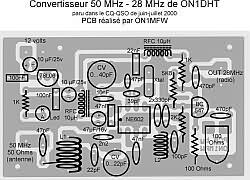
RXC50/10 SCHEMATIC
PARTS
IC1 = NE602, NE612, SA602A,
SA612A
IC2 = 78L06
T1 = BC547
C1 = 10uF/25v
C2 = 100nF
C3 = 100nF
C4 = 10uF/25v
C5 = 47uF/16v (tantaal)
C6 = 47nF (polyester)
C7 = 47pF
C8 = 22pF
C9 = 0...22pF (green)
C10 = 2n2
C11= 4.7nF
C12 = 0...40pF (white)
C13 = 47pF (poly)
C14 = 39pF (poly)
C15 = 47nF (polyester)
C16 = 330pF
C17 = 330pF
C18 = 100pF*
C19 = 4.7nF
C20 = 470pF
C21 = 470pF
P1 = 100 Ohm
R1 = 1k
R2 = 2k2
R3 = 100 Ohm
R4 = 5k6
R5 = 1k2
P1 = 100 Ohm
Coil specifications:
L1 = 7 wnd 1mm silver 9mm coildiameter (drill 7), tap on
1,5 wnd from the cold end.
L2 = 10 wnd 0,5mm email 5mm coildiameter (drill 4). Can be
tweaked if needed to change the bandpass range.
L3, L4 = shokes (RFC) 10uH +/- or use a ferite bead
Highlighted
The converter explained
The heart of the converter has
been built around Philips SA602 (NE602), a double balanced mixer
oscillator. This IC finds his applications in layer capacity
communication systems, cellular radio applications, RF data left,
VHF-transceivers, broadband LAN's ed. IC in a ordinary 8-pin
dual-in-line can be bought implementation (DIP) or 8-pin SO
(surface-mount miniature package) implementation. Both
implementation has a low cost. SA/NE602 a very low usage of only
2,4mA has! The total usage of the converter amounts to only 15mA.
Therefore also uncomplicated usable applications fed with
battery.
The mixer is Gilbert cell tip quadrant configuration which 18dB
can provide conversion gain. The built in Local oscillator work
to maximum 200MHz tank oscillator coordinated with a high Q or
crystal oscillator. The highest frequency which we can bring to
the input of this IC amounts to 500MHz.
In this project we apply a crystal retrieve oscillator. Frequency
stability is excellent and depends mostly of the surroundings
temperature crystal then the IC itself. As it happens, a very
ingenious and efficiently temperature compensating bias is built
in. Important to know is that the oscillator already has an
internal bias and therefore don't need extra dc-bias. Only at
very high frequencies a raised direct current can be necessary.
This one remedies by placing between the mass and resistor at pin
7 of a value of of 22k.
The NE602 LO works up to 200MHz and the input up to 500MHz,
therefore a huge 'reserve' is available since we use a much lower
LO input frequency. We want to convert, as it happens, 50MHz to
28MHz. This means therefore that we must mix with a frequency of
22MHz, meaning 50MHz - 22MHz = 28MHz output. To allow the
converter to be calibrated to obtain the exact frequency, a
regulable condenser of 40pF (C7) is added to the oscillator. With
this you can vary the termination frequency of the converter
+-300 Hz.
Without much adapting you can also use the more currently
available 24MHz crystal, but then the termination frequency of
the converter will be 26MHz ipv 28Mhz (24MHz LO + 26MHz OUT =
50MHz IN).
The Gilbert cell is a differential amplifier which has balanced
cell feeds. The differential gives extra gain and stipulate the
noise number as well as the strong indicator behaviour of the
recipient/converter. And these processes values up to -199dBm
with 12dB S/N ratio. The symmetrical RF input (pin 1 and 2) has
internal bias, thus we avoid external DC bias (to see C10 and
C15)! THE RF input amount to capacitantie 3pF. There we connect
single-ended coordinated LC-kring with parallel a resonance a
frequency of 50MHz. These can peaked to best reception with C9.
This is done best on a frequency where we want best sensitivity,
for example 50,220 MHz. To start, move C9 in the middle position.
When we have wound the coil L1 correctly, C9 does not need much
to be adjusted. If there is no station to tune in to, then
regulate C9 till you hear maximum noise.
To have a 50 ohm input by means of C7 and a tap at 1.5 turns from
the cold end of the coil. Of course you'll need on 50MHz tuned
antenna too HI.
The sensitivity of the converter amounts to 0.22uV at 12dB SINAD.
Third-order the intercept point is -13dBm. This is approximately
+5dBm output interception because of the RF gain.
The mixer has an internal DC-bias, by means of we connected the
output (pin 4 and 5) with a 1k5 resitor to Vcc. Disengaging of
the bias happens by means of C16, since we exploit here only a
single termination instead of a balanced output. A balanced
output will improve something, but to keep the schematic diagram
simple, I have not applied this.
To allow only the 28Mc signal to pass through to T1 and into your
radio I added a bandpass filter made out of C16,C17,L2 and C18.
How crazy it may sound it actually improved the gain too.
The termination capacitance of the mixer (pin 5) amounts to
1.5kOhm. Given the termination indicator and the RF output
voltage is a bit on the low side to connect directly to the
recipient (radio), there is a amplified step to added which
exists from a single BC547 transistor and als serves s a buffer
between your receiver and NE602. With P1 one regulates the
termination level (amplification) of the converter according to
the entrance sensitivity of your communication receiver. The
ideal setting is when we have the best singla/noise ratio. For
the most the centre setting of P1 should be sufficient. An
signal/noise ratio improvement can be made by using dual-gate
mosfet ipv BC547(or BC338). The noise number of SA/NE602 is 4,6dB
at 20°C and T1 ads its own noise level to it, as a result we end
up with an average noise number of approximately 5dB.
Bandpass filters out all
unwanted frequencies from the mixer
C18 and L2 acts like a bandpass in this schematic. It passes
signals approx. 26...30MHz. If using another LO frequency it
could be needed to tweak C18. So it isn't a bad idea to
uses a variable capacitor (trimmer) to fine tune the bandpass in
this case.

More about the SA602 (NE602, SA612) in this project
The SA602A is a Gilbert cell, an
oscillator/buffer, and a temperature compensated bias network as
shown in the equivalent circuit. The Gilbert cell is a
differential amplifier (Pins 1 and 2) which drives a balanced
switching cell. The differential input stage provides gain and
determines the noise figure and signal handling performance of
the system.
The SA602A is designed for optimum low power performance. When
used with the SA604 as a 45MHz cellular radio second IF and
demodulator, the SA602A is capable of receiving -119dBm signals
with a 12dB S/N ratio. Third-order intercept is typically -13dBm
(that is approximately +5dBm output intercept because of the RF
gain).
Besides excellent low power performance well into VHF, the SA602A
is designed to be flexible. The input, RF mixer output and
oscillator ports can support a variety of configurations provided
the designer understands certain constraints, which will be
explained here.
The RF inputs (Pins 1 and 2) are biased internally. They are
symmetrical. The equivalent AC input impedance is approximately
1.5k || 3pF through 50MHz. Pins 1 and 2 can be used
interchangeably, but they should not be DC biased externally.
The oscillator is capable of sustaining oscillation beyond 200MHz
in crystal or tuned tank configurations. The upper limit of
operation is determined by tank “Q” and required drive
levels. The higher the “Q” of the tank or the smaller
the required drive, the higher the permissible oscillation
frequency. If the required LO is beyond oscillation limits, or
the system calls for an external LO, the external signal can be
injected at Pin 6 through a DC blocking capacitor.
External LO should be at least 200mVP-P. It is important to
buffer the output of this circuit to assure that switching spikes
from the first counter or prescaler do not end up in the
oscillator spectrum. The dual-gate MOSFET provides optimum
isolation with low current. The FET offers good isolation,
simplicity, and low current, while the bipolar transistors
provide the simple solution for non-critical applications. The
resistive divider in the emitter-follower circuit should be
chosen to provide the minimum input signal which will assure
correct system operation.
Notes:
Tune to the desired bandpass frequency (50Mc) with
C9 until you have the best reception.
Use C12 to calibrate the output frequency to your receiver. The
output frequency can be adjusted up to 300Hz.
The output HF-level can be adjusted with P1. Regulate it
according to the sensitivity of your receiver.
Other output frequencies can be
set by changing the 22MHz Xtal: Example: output frequency is 26
MHz then you use a 24 MHz Xtal (50MHz - 24MHz = 26MHz).
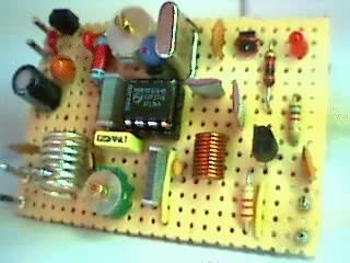
Build the converter in a metal box and use small connections
between the parts.
Important: use only a antenna designed for 50MHz! A simple dipole of around 3 meters in length (two times 1,45 meters) will work just fine if the propagation is there. Look at my homebrew site for a 3-element beam that works much better then a dipole and gives more gain, or a my 1/2 lambda vertical antenna.
More info about the 50MHz band (6 meters, the Magic band...) can be found at my site at MagicBand or Radioamateur Info.
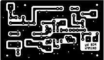
PCB:
A PCB has been designed for this project by ON1MFW. E-mail me for
detailed high resolution image of the PCB. Example: PCB-parts side PCB layout
Detailed information and manual (in Flemish (Nederlands)) ON6MU's 50MC CONCVERTER MANUAL
Technical graphs:
This project has
been published in CQ-QSO (in Dutch and French) the ham-radio
magazine of the UBA.
Magazine 06-07/2000 pages 14,15,16 and 17.
More about his:
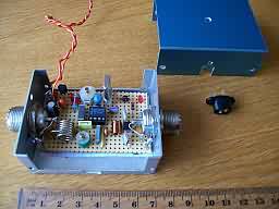
How
Geoffrey F4FVI made it:
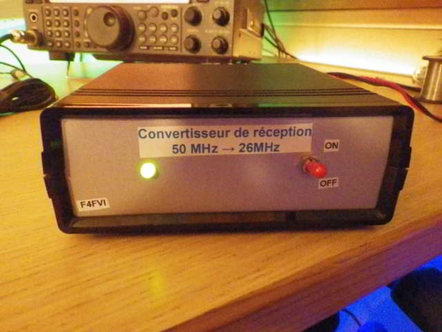
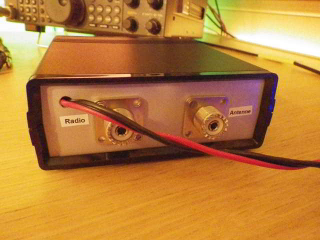
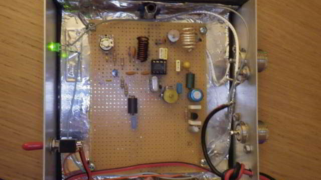
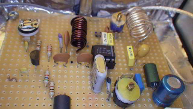
Thanks Geoffrey for the pictures!
Please take also a look at my 70Mc converter
Note: if you want to
commercialise, publish or distribute this project
then you need to ask permission to do so.
Back to
![]() Homepage
Homepage