100W PA for 70cm
by
DL4MEA
Since
the closes digipeater at my portable QTH was
switched off I had to search for another. I had
great troubles to reach these since i can only
use simple antennas on the balcony to the
backyard there. For every solution there was too
less power. After many thoughts to buy a 35W
tranceiver or to buy a power amplifier I decided
that this is too much money. The solution was
found when I saw 70cm power modules M67729H2 for
about DEM 30,- each. These were not specified for
430-440MHz but seemd promising according to the
datasheet. At the same time I found a solution to
run 4 of them in parallel. So this was the final
goal. For about DEM 200,- I got a fine PA with 2W
input and 100W output, which allows me to
continue to use my handy.
The principles
of the parallel connection of these power modules
are not limited to the ones I use. I am very
awaiting that one who tries to connect 4 pieces
of high power modules capable for SSB and a 5th
as driver, that would result in a PA with 5W
input and app. 260W output.
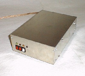
Front View
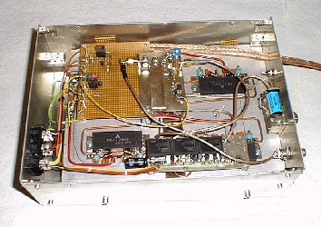
Circuit
Description:
Two power moduls are parallel connected, which
results in a 25 Ohms impedance. Using a quarter
WL line this impedance is transformed into 100
Ohms. There again two of these are parallel
connected and deliver the needed 50 Ohms. There
is the same connection at the input and the
output.
For the connections I use Semi-Rigid cable (SR).
Since I had lots of 2mm diam. cable I took that.
But I suggest to use thicker one at the output,
since mine becomes a little bit warm.
The T-connections are made with copper foil as
connection of the screens. First dismantle the SR
for about 1-1.5mm. Then tin the shield and cut
the (growing) isolation. After that solder the
three inner wires, place a small piece of foil
below and solder the SR screens to it.
The modules are also mounted and connected with
copper foil. For each module take a piece of
copper foil and place it between the module and
the heat sink. Between each there is a small
amount of heat compound. The ground connections
of the module are directly soldered to the foil,
also all blocking capacitors and the ends of the
SR. The 10pF trimmers are used to align the SWR
and to align the coupler. The power supply of the
modules is separatly connected for the final and
the driver stage. The driver stage's power is
supplied by the VOX unit, the final stages's
power is connected to the DC input straigt
forward.
By the way, I mounted my modules wrong, since I
have the long wires on the output side. Take care
to have the two short wires which connect two
modules together at the output side.
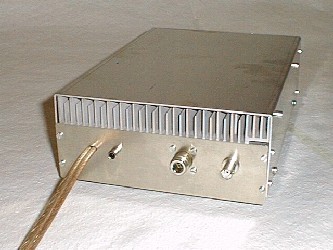
Back
View
NOTE:
The Mitsubishi modules M67729H2 that I used have
the output on the left, the input at the right
side. There are older datasheets where this is
noted wrong. Since I prefer closed cabinets
against open heat sinks because they are easier
to staple and since there are only short
transmission periods in PR I used only a small
heat sink. This is cooled by a temperature
controlled blower. Further on there is an
overtemperature detection on the VOX decision
logic "VOX4B" which can disable all.
by
DL4MEA
|