One
of the simplest ways to improve the long term frequency stability of a
receiver is to ensure good thermal stability of all the oscillators
used in the receiver, this can be accomplished with the use of an
"oven" to regulate and maintain the temperature of the oscillator
circuits or frequency determining components within the
oscillators. More on the subject of temperature stabilization of
oscillators can be found here. Crystal
ovens for QRSS
applications.
If
the receiver you
choose for QRSS reception does not have a temperature stabilized
L.O./B.F.O. it may still give acceptable results if it is left to
"warm-up" long enough such that the receivers internal temperature can
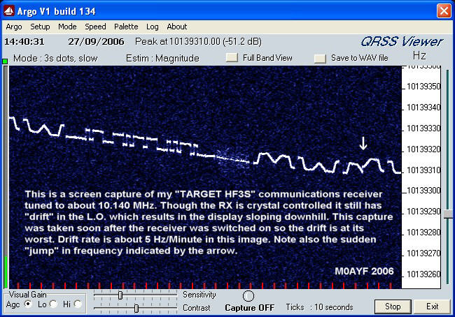
stabilize. The Target HF3S I used for some of the example images shown
above has acceptable frequency stability for QRSS reception if it is
left to warm-up for about six hours! I found it also helps to keep the
shack door closed as well in order to keep the room temperature
stable.
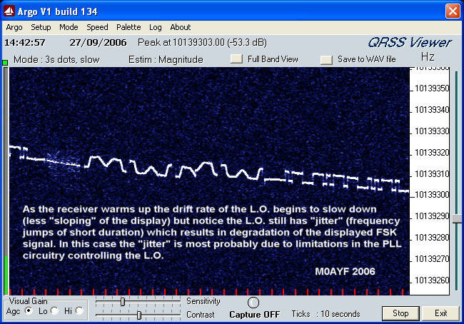
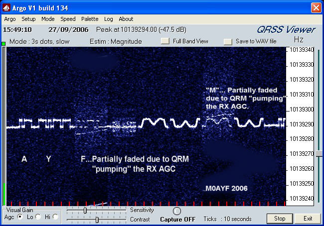
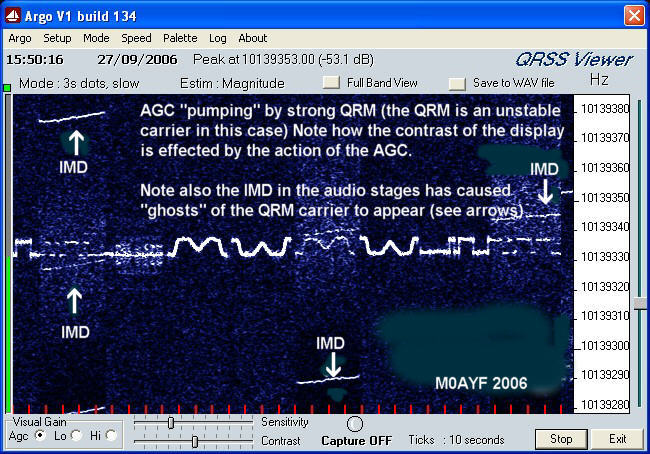
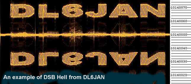
Another
undesirable "feature" of some receivers is the effect of distortion
(I.M.D.) within the audio stages of the receiver. In normal amateur
radio service the audio stages can have several percent of distortion
and the effects often go unnoticed since they have little or no effect
on the intelligibility of narrow bandwidth telephony (speech) or
telegraphy (CW) but with QRSS those unwanted IMD products can manifest
themselves as unwanted "ghost" signals when viewed on the PC running
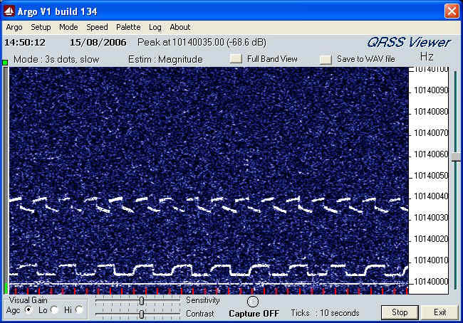
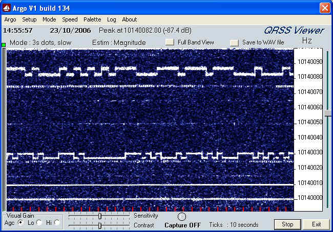
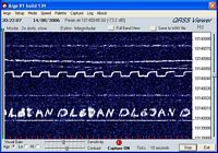
QRSS software. The image on the right (above) shows the effect of AGC
"pumping" and also shows some of the IMD products caused by the strong
signal used to induce the AGC action, the unwanted "ghost" signals are
shown arrowed.
So,
for best results when receiving QRSS use a narrow I.F. bandwidth
setting and make sure the AGC is turned off. Reduced BW will help to
reduce the effects off unwanted signals and improve QRSS reception.
Since the QRSS sub-bands are generally no more than 100 Hz wide it is
quite acceptable to use a BW of say 300 to 500 Hz as might be used in
CW operation. If your chosen receiver does not have such narrow
bandwidth settings you may still be able to obtain acceptable results
with QRSS though much depends on the level of band activity and just
how strong the QRM signals are.
So,
to sum up, here are some of the desirable qualities for a good QRSS
receiver which are additional to the requirements for regular amateur
radio receivers.
1)
Exceptionally good long term frequency stability.
2)
Good short term frequency stability (No "jitter" in the LO/BFO etc)
3)
Good sensitivity consistent with good dynamic range.
4)
No AGC or AGC switched-off.
5)
Low IMD in the audio stages.
6) A choice of I.F. bandwidths
with at least one CW bandwidth setting of 500 Hz or
less.
If after reading these
notes you decide that nothing you currently have in your shack is
suitable for QRSS reception then you may wish to consider home brewing
a receiver. As indicated earlier, successful receivers for QRSS
reception need not be complex and can be built using readily available
components.
An example of a
simple home brew direct conversion receiver for 30 Mtr QRSS reception
can be found here.
A simple 30 Mtr direct conversion
receiver for QRSS reception.
Here are two example images of several QRSS signals obtained
using the
simple (but very stable) direct conversion receiver mentioned above.
Antennas for
QRSS reception.
In
many cases the choice of antenna that will be used is dictated by an
individuals QTH, personal preference, local restrictions or the space
available for antennas. My preference for any receiving
antenna is to have some form of "balanced" antenna such as a
dipole. At
my QTH local noise/QRM is a dominant feature on all of the
H.F. bands
up to about 22 MHz and I have found that the use of a balanced
receiving antenna helps to reduce the local QRM considerably. If you
happen to live in an electrically "quiet" QTH then an antenna which
"captures" as much of the signal as possible may be your preference,
you may even prefer to use a vertical antenna with a view to picking up
more of the low angle radiation.
If
you are new to QRSS and currently have no antenna for the 30 Mtr band
then I would recommend a trusty dipole as a good starting point. Mount
the dipole as high as you can and if possible keep it as far away from
any known local QRM sources such as TV sets, Computers etc. Use a
balanced feeder all the way back to the shack or a balun at the dipole
center with a good quality
coax feeder back to the shack. A very interesting design for a compact
30 Mtr dipole appears on the web pages of I2NDT (Claudio), this antenna
is suitable for both RX and TX purposes. A link to his page appears
below.
Interesting
Dipole Antenna design by Claudio (I2NDT)
If
you are troubled by local noise then you could try a small
active loop
antenna. I use an active loop antenna here and have found it to be very
successful at defeating local QRM. Several choices are possible, a
passive resonant loop antenna which has a high "Q" and narrow BW, this
helps to reduce the level out-of-band signals and helps to prevent IMD
in the front end of the receiver which can arise from powerful SW BC
stations. Even low levels of IMD can cause "ghost" signals to appear
which can be mistaken for QRSS carriers. Another form of loop antenna
is the compact "active loop" antenna, the "active" part is an RF
pre-amplifier which is used to compensate for the small dimensions of
the receiving loop. A compact active loop can also be made resonant and
because
of its small physical size it needs less space than other forms of
antenna. A variation on the resonant active loop is the broad-band
active loop, this is also a "balanced" antenna and
therefore resistant to local QRM but has the added advantage of being
able to cover the entire L.F./H.F. spectrum. This is good if you have
limited space for antennas and wish to pursue QRSS and general SWL
activities. This has been the case here at M0AYF where a broad-band
active loop has been used for a couple of years now with good results. The
possible disadvantage of the broad band active loop is that it
risks IMD in the front end of the receiver due to the high strength of
signals which are far removed from the frequency of interest. IMD has
not been a problem here at M0AYF and if your
chosen receiver has good IMD performance then the broad band loop may
be a choice worth consideration. The physical location of the loop (be
it
active/passive/resonant or non-resonant) should be chosen with the same
considerations as for the dipole mentioned earlier. If you are
interested in experimenting with a "wide bandwidth active loop
antenna" then follow the link below.
A Wide Bandwidth
Active Loop Receiving Antenna.
Software for
receiving QRSS.
There are currently a number of software packages in existence which are suitable for viewing QRSS signals
but since this web page is intended for those with no prior experience
of QRSS I will describe the use of just one such software package. First of all, go to the links page on this website and look under "Software for QRSS" then follow the link for "Argo" which is a very user friendly piece of software for viewing QRSS signals.
Download Argo and follow the instructions for installation on your computer. If you are unsure how to connect your receiver to the computer then return to the links page and look under the heading "Connecting your computer's sound card to your receiver" and follow the links which describe methods of connecting a radio receiver to a PC. Ounce you have mastered the connection of the radio to the sound-card on your PC you will then be ready to start using the Argo QRSS package. In addition, you will now be able to use many other similar sound-card based softwares for modes such as RTTY, WSPR and FT8 etc.
Links to other QRSS web pages and resources.
Having connected your radio receiver to your P.C.s sound card you
should now check that the P.C. is getting the audio signal from your
receiver. This can be done in several ways but perhaps the easiest
method is to "loop through" the sound card and check you can hear the
sound from your radio receiver also coming out of your P.C.'s
speakers. The sound should be set to a reasonable level such that it is
loud enough to be heard but not distorted. Having confirmed that the
receivers sound is reaching the P.C. correctly you can now attempt to
tune in a test signal with which to check the operation of Argo. Look for a weak broadcast station carrier or
other stable signal
that is weak but constant and set the receiver so you get an audio
"beat
note" with a pitch of around 800 Hz. Now launch Argo
and using Argo's "Full Band View" you should see a vertical white line
(or thick white bar) running vertically down the screen at around 800
Hz. You should find that by adjusting the clarifier control the pitch
of the "beat note" changes and the position of the white
line/bar
also changes. This will indicate that the receiver/P.C. sound card
connections are correct. If you have problems then re-check the
connections to your receiver/P.C. sound card and/or consult the
instruction manuals for your P.C./Sound card and receiver.
If
you don't know exactly where to look for QRSS signals then its like
"looking for a needle in a haystack" so if your new to QRSS I would
suggest looking around 10.140 MHz but before you do so please check the
calibration of your receiver. The indicated frequency on the receivers
frequency display is no proof that it is the true frequency
being received. An error of only 100 Hz could mean the difference
between successful reception of QRSS or not seeing anything at all. An
error of +/- 100 Hz may be fully acceptable for CW/SSB
working but for QRSS
reception an error of +/- 10 Hz would be more acceptable. To
check your receivers frequency display accuracy you can
use one of the methods listed below for calibration.
1) One of the many frequency standard broadcasts (MSF on 60 kHz, WWV on
10 MHz etc)
2) A GPS disciplined
crystal oscillator.
3) Use an existing QRSS
signal of known accuracy as a comparative reference.
4) Use one of the "Propagation Beacons" for frequency calibration. (Beware of this
method!)
1) One of the many frequency standard broadcasts (MSF on 60 kHz or WWV
on 10 MHz)
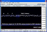
The short list of
options above are
intended only as a guide, you may prefer to use a different option. My
own current preference is to use a harmonic of a 10 kHz square
wave signal derived from a divided down 6 MHz crystal oscillator which
is phase locked to MSF on 60 kHz. The design I use is based on a design
built by Andy (G4OEP) which can be found here. MSF "Off-Air" Standard.
My
version of the MSF phase locked reference can be found here.
An MSF Locked Frequency Standard for QRSS Calibration.
2) A GPS disciplined crystal
oscillator.
The second
option above is becoming increasingly popular due to the falling cost
and availability of GPS systems. Many of the units available provide an
O/P which is phase locked to the atomic clocks used in the GPS
satellites. More information on this option can be found here.
A
GPS Disciplined Oscillator.
3) Use an existing QRSS signal of
known accuracy as a comparative reference.
Of the four possible
methods listed
above number three is perhaps the simplest but you have to be sure that
the QRSS signal you choose has a known frequency and is very stable.
4) Use of
"Propagation Beacons" for frequency calibration (Beware of this method!).
Before we go any
further, a
cautionary note. In my own early experiments with QRSS viewing I had
been using the IK3NWX propagation beacon on 10.1418 MHz as a frequency
calibration source. The receiver I was using at the time was a Target
HF3S, this is the same receiver used for the examples of a poor
frequency stability receiver shown above. Because of the wide I.F. B.W.
of the receiver (around 4 kHz or more) I was able to see the IK3NWX
beacon using Argo in "Full BW" mode while simultaneously being able to see the QRSS
sub-band. By adjusting the receiver BFO such that IK3NWX appeared at
around 2.5 kHz in Argo
I would then know to look for QRSS between 700 and 800 Hz which equates
to 10.140000 - 10.140100 MHz. This worked quite well but on some
occasions it was evident that I was "missing" part of the QRSS band. It
turned out that it was the IK3NWX beacon which had "drifted" very
slightly in frequency. This beacon frequency drift was in addition to the drift in my own receiver.
So, if you choose a propagation beacon
for frequency calibration then first check up on its frequency
stability. It is only fair to point out that the IK3NWX propagation
beacon does not drift very much and by most standards actually has
excellent frequency stability. The very slight changes in frequency of
the beacon only become apparent when compared
to other more
stable frequency sources. If you are in the EU then using the
IK3NWX propagation beacon
would help to put you in the right "ball park" for QRSS viewing in the
absence of one of the other frequency calibration methods listed
above. I should also like to add that the IK3NWX propagation
beacon is an excellent indication of propagation conditions and at this
location (IO93oj) it has proved to be a very accurate indicator for the
possibility of receiving EU QRSS signals at any given time. I have
found that if IK3NWX is weak but detectable in Argo then it
is fair to assume that
other EU QRSS signals will be detectable here in the UK.
Probably 90% of the QRSS activity takes
place in the 30 Mtr amateur band between 10.140000 and 10.140100 MHz
(100 Hz window), this is not an "official"
sub-band, it simply happens
to be where most of the QRSS activity takes place. The propagation
conditions on this band are such that contacts from just a few hundred
kilometers to thousands of kilometers are possible even with modest
antennas
and low power levels. Activity also takes place (to a lesser extent)
in the 40, 80 and 160 Mtr bands. The exact frequencies are often linked
to readily available crystals, for example QRSS signals in the 80 Mtr
band are often located around 3.580 MHz and in the 40 Mtr band 7 MHz
crystals are often used so the signal can be located within the first
100 Hz or so just above 7 MHz. There has also been activity
in Italy
within the 10 Mtr band using very low power (a few mW) from "canned"
crystal
oscillator
modules. There are no fixed rules on the exact frequency or bands used
for
QRSS but given the nature of QRSS it makes sense to co-ordinate
activity as much as possible with other enthusiasts in order to have
the best chance of receiving other peoples signals or having your own
signals
received by others. To that end there is a very active forum on
the Internet dedicated to QRSS activity which can be found here.
Details
for
subscribing to the QRSS forum can be found here.
A
number of QRSS enthusiasts
have HF receivers connected to a PC which then uploads real-time screen captures
of qrss signals to
the world-wide-web. Since both the number and status of these on-line resources
may vary
Scott Harden (AJ4VD) and Andy (G0FTD)
have created "QRSS Plus" which brings together as many of the
on-line grabbers as possible onto a single page. Because of the
unpredictable nature of radio propagation we do
not promise you will see QRSS signals every time you view the grabbers
so its worth checking back from time-to-time.
Link to
Scott Harden (AJ4VD) and Andy (G0FTD) "QRSS Plus" page.
What to look for.
As already stated, most
of the HF QRSS activity will be found in the 30 Mtr band between 10.140000
and
10.140100 MHz.
First
tune your receiver to 10.140 MHz (USB). Then, using a
stable test carrier or signal generator set to 10.140 MHz loosely
couple the signal to the receiver antenna. Next adjust
the BFO/Clarifier control to give a "beat note" of around 800 Hz.. The
choice of 800 Hz for the beat
note is not critical, its just a fair bet that 800 Hz will be well
within the audio bandwidth limits of the receiver/sound card. If the
beat note
is set to low (say 250 Hz) it could be attenuated slightly by the
receivers
audio filtering, if the beat note is set to high (say 3000 Hz) then it
will fall outside of Argo's working window. At this point it is also a
good idea to check Argo's settings are the same as those in the image
below. For general QRSS viewing these settings have been found to be
optimal for most conditions and are recommended as a good starting
point.
Now using Argo's
"Full
Band View" look
for a continuous vertical line between 800 and 900 Hz, this
is your test signal. The appearance of a vertical line between 800 and
900 Hz assumes you have set your receiver to 10.140 MHz, checked the
receivers frequency
calibration and also set the receivers audio beat note to 800 Hz. Now
position the mouse pointer on the vertical line and "click"
the left mouse button, this should then change Argo's display to a
horizontally scrolling window just over 100 Hz wide. After a few
minutes you should see a horizontal white line appear on the display
which corresponds to your test signal. How straight this line appears
depends on the stability of your receiver/test signal. Now switch off
the test
signal and go back to Argo's
"Full Band View" and look for
similar (though possibly weaker) vertical lines and again position the mouse pointer on
one of the vertical lines and "click"
the left mouse button to change Argo's display to the horizontally scrolling window. After
a few minutes
you should have enough of the signal to look at to decide if it is a
QRSS signal or not. Do not be discouraged if you don't see
QRSS
signals on your first attempts, a great deal depends on propagation,
current levels of QRSS activity, QRM levels etc.
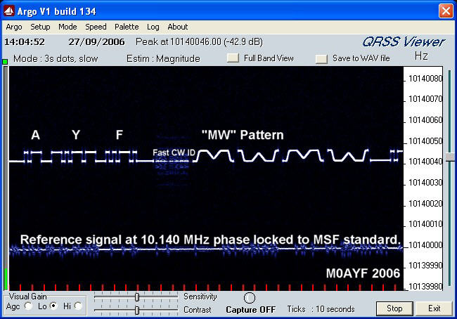
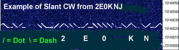
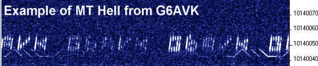
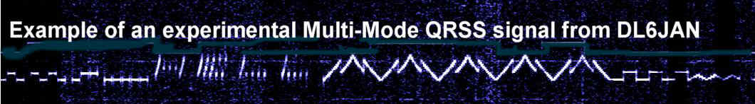
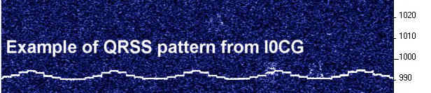
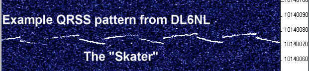
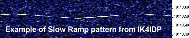
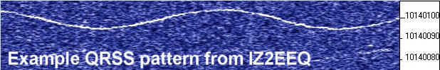
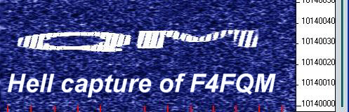
Some examples of QRSS signals are shown below, they will give you an
idea of the sort of signals you might expect to see and the various
modes that are sometimes used. Various patterns are popular in QRSS
operation because they "stand out" better under weak signal conditions and the
patterns used are also a good way to "personalize" a QRSS transmission,
a sort of QRSS signature.
Click on any
of the thumbnails below to see a higher resolution image.
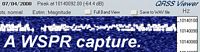
WSPR (pronounced "whisper")
The WSPR (pronounced "whisper") capture
shown above is a recent development in the world of QRSS which
uses software running on a PC to generate a number of audio tones
with frequency spacing of only a few Hertz. These tones can be fed into
the microphone input of an SSB
transmitter in order to transmit a very narrow bandwidth (less than 10
Hz) coded signal.
While the coded signals can be viewed using Argo (or similar software)
the signals are intended for decoding using the WSPR software. The
coding of the signals conveys information such as call sign and
signal-to-noise ratio.
The software was written by Joe Taylor (K1JT) who also wrote the very
successful WSJT software used for meteor scatter experiments.
At
the time of writing (April 2008) the software is still developing with
many innovations and improvements still to come. A full description of this mode
is not possible because of the speed with which new developments to the
software keep appearing so for the latest information please go to Joe Taylor's WSPR download and
information page.
Link to WSJT-X (Includes WSPR) download and
information page.
Most WSPR activity within the 30 Mtr band is (by voluntary agreement)
located in the 100 Hz segment directly above the
10.140000
to
10.140100 MHz QRSS sub-band. So for WSPR activity look
around
10.1400100
to
10.140200 MHz though (at the time of writing) a number of stations are
operating outside of these limits due to the "congestion" on the band
from other WSPR operators, such is the popularity of this mode. A
number of operators are also using equipment with poor stability (by
QRSS standards) so they tend to "drift" outside of the agreed limits.
Also (at the time of writing) many of the WSPR operators are using far
to much power! WSPR is a very sensitive mode requiring very low power
(500 mW is normally more than enough) but many new WSPR operators who are also new to
QRSS are running several Watts! To be fair this can be due to the use
of commercial equipment which is not capable of power reduction below a
few Watts but the result of using to much power is to "swamp" the screens of QRSS viewers.
A good
time to look is at
the week end when activity is normally at its highest. There is
sometimes activity during the week too but if you are new to QRSS and
looking for the
first time then the week end offers the greatest possibility of
success. The time to look depends on the the time of year, propagation
conditions etc so its a good idea to learn about the propagation
characteristics of the 30 Mtr band. I also recommend checking some of
the on-line resources mentioned towards the end of the "Where to look for QRSS"
section so you will know what the level of activity is likely to be.
QRM from contest stations (both CW and RTTY) can be a problem so try to
avoid those week ends when the contests are running. Though we share
the 30 Mtr band with other radio amateurs the QRM is normally not too
bad with the exception of contest week ends already mentioned. It is
not unusual for the odd CW or RTTY QSO to appear right in the middle of
the QRSS segment but generally (with the exception of contests) the
operators finish the QSO within minutes and move on. The slow nature of
QRSS means that over a period of a few hours several QRSS signals may
be copied with only sporadic interruptions by other band users. Most of
the time the other band users are unaware of the QRSS signals because
they are often sub-audible.
My own success at receiving QRSS was very slow to start with,
this
was partly due to my lack of experience with this mode and partly due
to the use of a receiver that had excessive frequency drift.
It took
me several weeks before I saw my first confirmed QRSS signals.
Following my first successfully received QRSS signals the search
process became much quicker and easier, within a few more days finding
and capturing QRSS images became almost routine.
A vintage QRSS sound sample recorded on Monday the 23rd of October 2006 at
around 11:00 UTC.
If you are having difficulty in finding or tuning into QRSS signals
and would like a sample audio file for testing Argo then I can offer you a 6 minute QRSS sound sample in Windows ".wav" format.
Due to storage limitations here on QSL.net I was unable to make the file available for direct download but if you need a copy of the sound file for testing then please feel free to send me an e-mail request and I will send you the "zipped" file which is 4.57 M/bytes in size. My current e-mail address is linked at the bottom of this page.
Ounce you have the file safely stored on your PC then unzip the file and follow the instructions below in order to view the QRSS signals.
Because of local QRM at the time the recording was made you may find
that locating the QRSS signals is "challenging" but this recording
serves as a good example of what to expect in a "noisy" environment and
should provide a good signal to test/explore the features of Argo.
When you receive the file and have successfully unzipped the audio sample the next step is to select Argo's "Setup"
menu, then go into the "Select Input" menu followed by "Choose real
time
input" sub-menu. Now select the "What U hear" option and make sure all
other inputs to your P.C. sound card are disconnected. If you now play
the sound file you should be able to hear the sound playing in the
speakers of your P.C. and at the same time you should be able to view
the QRSS signals in Argo as if it was "live" audio from your
receiver.
Listening to the sound file you will hear a faint "buzzing" sound which
is the QRM from local T.V.'s and P.C.'s etc. You will also
hear some static from distant thunderstorms and if you have
exceptional hearing you may be able to hear the faint whistle of the
QRSS signals at around 1660 Hz. It may be that all you can perceive is QRM and static? But follow the instructions below and the QRSS signals should become perfectly visible.
The sound sample was recorded on Monday the 23rd of October 2006 at
around 11:00 UTC using my QRSS 30 Mtr direct conversion
receiver.
Because
of the direct conversion receivers local oscillator offset the QRSS
band appears centered around 1660 Hz. If you select Argo's
"Full Band View" and look in the area of 1660 Hz you will see a couple
of unbroken vertical lines, they are the QRSS signals. You will also
see many more broken vertical lines which are of much greater
signal strength from around 400 to 1900 Hz. They are caused by local TV
QRM and my own P.C. monitors harmonics. If you position the mouse pointer at a point corresponding to 1660 Hz and
"click"
the left mouse button, this should then change Argo's display to a
horizontally scrolling window just over 100 Hz wide.
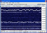
You should now have a
horizontal scrolling display which shows the QRSS band between 10.140000 to
10.140100 MHz
just as I viewed it here at the time/date shown above. If you want the
horizontal display to show the correct frequency then enter the
following frequency offset (see Argo's instructions) of 10138385 into
Argo after which the horizontal window will then show the correct 30
Mtr band frequency plus or minus a few Hz due to the tolerance in the frequency
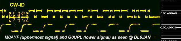
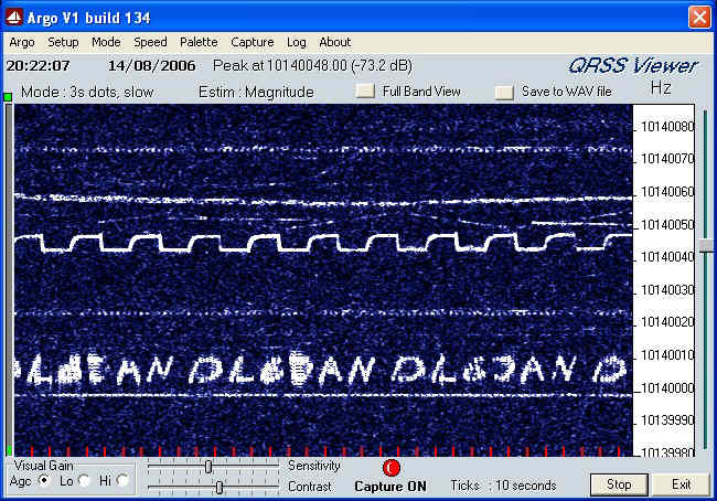
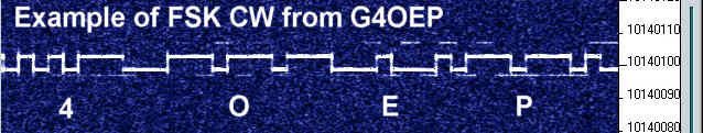
of your sound cards clock oscillator. You should be able to resolve two
FSK CW QRSS signals (plus QRM from TV/Computer etc), the FSK CW signal
uppermost (about 10.140080 MHz) is that of G4OEP. Notice the
"spreading" of the signal which is probably due to arrival via multiple paths. Some of those additional paths may also have some Doppler shift. For me (here in the UK) this was reception of a "short
skip" signal. The lower signal
(about
10.140027 MHz) is that of DL6NL which is also an FSK CW signal and
remained visible for most of that day.
I replayed the audio sample a few hours after the recording was
made
to make sure it was valid and also to take a screen capture of the displayed signals using Argo,s screen capture feature. The captured image is
shown below and gives you an idea of what you should see when you replay the audio
clip as described above.
Closing comments.
The
information presented here is by no means exhaustive or complete but
hopefully it will give you some idea of the requirements for successful
QRSS reception. Based on my own experience it is possible to receive
QRSS signals with very modest equipment and worry about refinements
later. For
example, a receiver which has a modest amount of frequency drift will
often still produce good results if the user is willing to accept that
it may need constant re-tuning over a period of time. Such a receiver
only becomes problematic when you want to leave the system "capturing"
images automatically over extended periods. In such a case of
"unmanned" operation it may be found that the signals drift outside of
the
capture window and with no one around to correct the tuning some of the
QRSS
signals may be missed.
I hope this has been helpful but if you still have unanswered questions
then please feel free to contact me and I will be happy to try and
answer any
questions relating to QRSS. Alternatively have a look at the "links"
section of this web site and also take a look at some of the other QRSS
"Knights" web sites,
this may help you to see the subject of QRSS from a
different perspective. If you decide that QRSS is for you then "welcome
aboard" and good luck with any QRSS projects you may undertake.