A MANUAL REMOTE ANTENNA TUNER
or A REMOTE IMPEDANCE MATCHING NETWORK
Pete Wokoun Sr., KH6GRT, 10/2014
1/2017: Updated some front panel controller and outside
pictures.
10/2017: Added inductor position curves, original article
link, and sources for hard-to-find items.
This project is a result of reading about Joe Ostrowski
KI5FJ and his Remote Impedance Matching Network article appearing in the October
2011 issue of QST. Thanks to Joe for his help and detailed information.
I used an 88 ft dipole up 32 feet fed with about 90 ft of
600 ohm open feed line. The antenna tuner and a 1:9 balun were located in the
shack. I needed to relocate the tuner and balun closer to the dipole to decrease
the amount of open line. I can run up to 600-800 watts so a high power tuner
is a requirement. My problem: high power automatic antenna tuners are expensive!
Joe's project was to make a manual remote antenna tuner. I suggest you read
the original article to get Joe's thoughts on how to do a remote tuner. Having
Joe's thoughts I'll explain where I deviated from his methods and went with
my tuner. You can view a pdf of Joe's original article by clicking HERE.
Use your back arrow to return here.
Our tuners use a differential capacitor that rotates through
all its values while the variable inductor rotates a limited amount. The resultant
effect is that "a wide variety of combinations of inductance (L) and
capacitance (C) are tried to match the antenna". In commercial tuners
this method is called the differential-T 2-knob tuner. The differential capacitor
Joe and I both used are from the MFJ-986 tuner.
Both the differential capacitor and variable inductor
are driven by motors controlled from the shack. Joe used old electric screwdriver
motors; I used 12 volt reversible gear head motors. I also needed to fit everything
into a 12 inch x 12 inch non-metalic junction box which would be located under
the roof eave. For my tuner the rotation speeds are as follows: In normal
mode the variable inductor takes 4 minutes to rotate its full 30 turns. The
differential capacitor takes 2.5 seconds to rotate a full 360 degrees. Another
way to state it, while the capacitor rotates a full 360 degrees, the inductor
only moves about 145 degrees, just a partial turn. In the slow speed switch
positions the motors run at half speed for finer resolution at the null points.
As Joe stated, this ATU design is a relatively simple
approach to impedance matching. In operation, while transmitting a very low
powered signal and observing the SWR in the shack, you adjust the L and C
remotely to achieve a low SWR to keep the losses low in the coax going to
the remote tuner, thus putting maximum power into your antenna.
Practically speaking, this tuner operates like this: You
search for matching by driving the L and C together in the forward or reverse
direction while watching the SWR. The SWR stays high until the L and C start
approaching a matching solution. Then the SWR starts gyrating up and down,
reaching a minimum SWR at one of these gyrations. I then stop driving the
L and C together and then drive each one separately going for that minimum
SWR just like any other manual tuner. When I find that minimum SWR point I
record that L POSITION indication so I don't need to search for it again.
When going to that position directly you only have to jog the C a couple of
times to get back to that sweet spot. You can use a low-powered signal from
your rig or an antenna analyzer to determine the L POSITION indications.
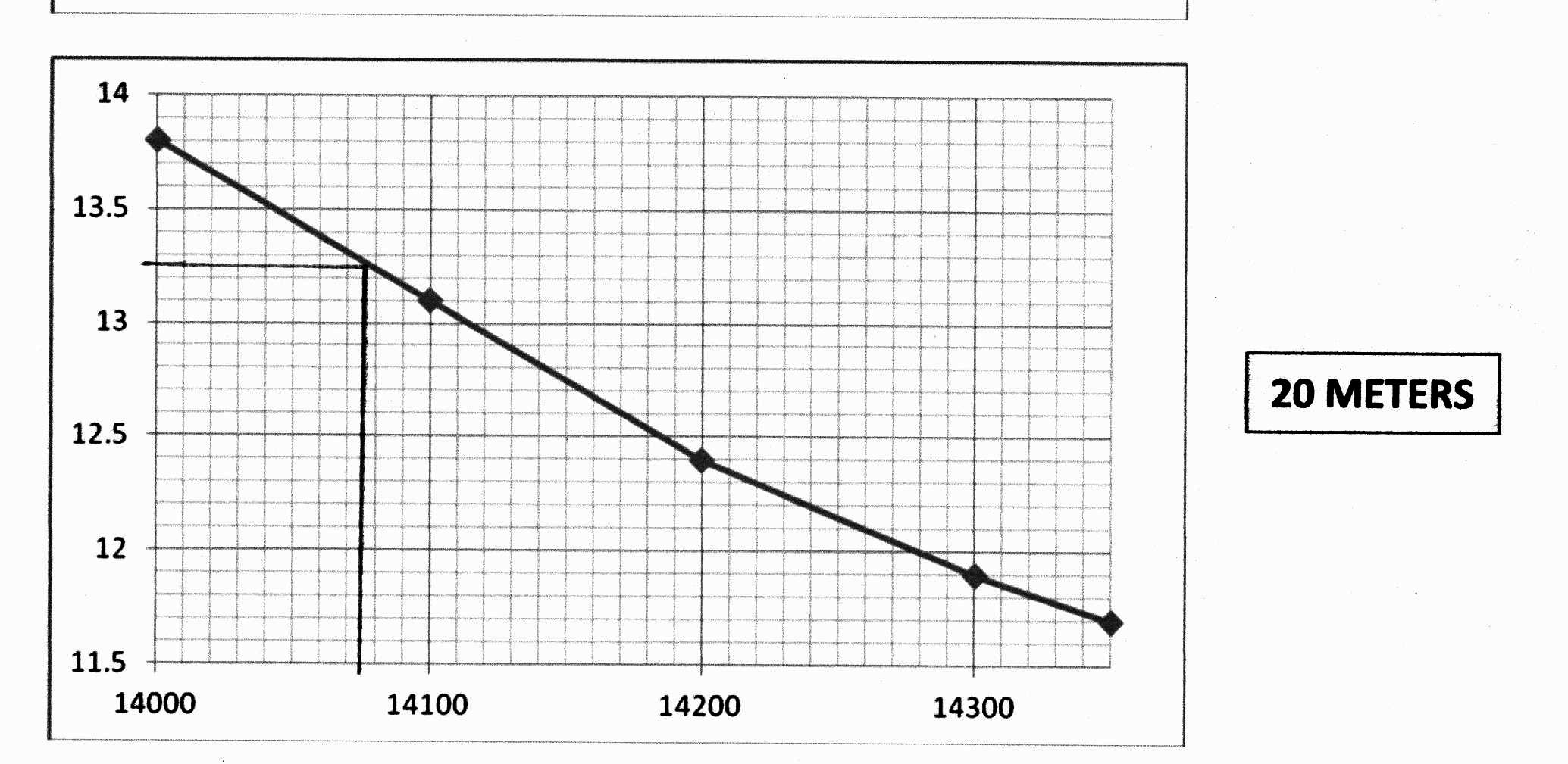
I eventually developed frequency vs. inductor position
curves from the stored L POSITIONS for all the ham bands. The required inductor
position is now just read off the curves. This is what the 20 meter band curve
looks like:
Block diagram of my initial system.
As it turned out it was only able to match the antenna
from 160 meters thru 12 meters.
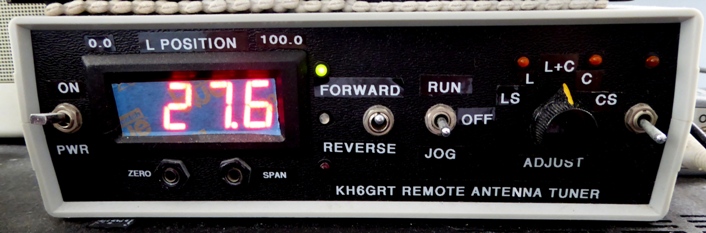
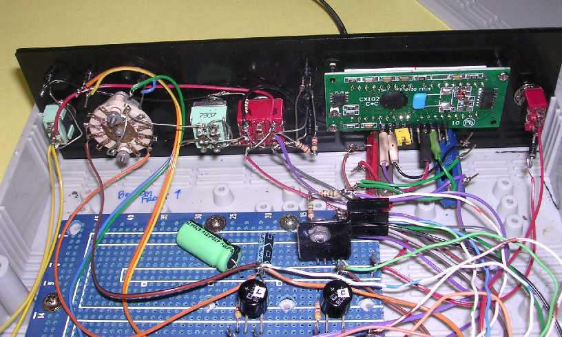
CONTROLLER:
The controller located in the shack controls the motors
for the variable inductor and differential capacitor. It controls which direction
the motors will run, whether to run the motors continuously, momentarily jog
them, or leave them off, and allows each motor to run together or individually.
Provisions are included to add a fixed inductance in series with the variable
inductor to give a wider range of inductances. A digital display is included
to indicate the variable inductor position from 0.0 % to 100.0 % so it can
be accurately repositioned. LEDs are included to indicate motor direction,
running direction, the adjusting component, and if additional inductance is
selected.
 The
RUN/OFF/JOG switch is a momentary switch in the jog position. A Jameco #317261
would work here.
The
RUN/OFF/JOG switch is a momentary switch in the jog position. A Jameco #317261
would work here.
The upper green and lower red LEDs next to the meter show
the selected direction. The middle green/red LED is lit only when running a
motor.
The forward direction is driving the inductor towards 100
%; reverse direction is towards 0 %.
Green LEDs are used in the FWD direction. Yellow LEDs show
what's turning.
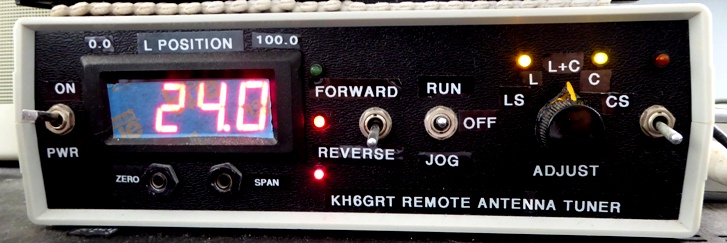
The ZERO and SPAN are panel mounted trimpots and set the
meter to the variable inductor end points of 0.0 and 100.0 percent. The output
of the position pot varies from 0.6 volts at 0% to about 4.4 volts at 100%.
The L+C position adjusts both the inductor and capacitor
together; the L and C positions adjusts each one individually; the LS and
CS positions are the inductor or capacitor individually running at a slower
speed.
Red LEDs are used in the REV direction. Yellow LEDs show
what's turning.
The 3-1/2 digit LED panel meter, model CX102B, is also from
Jameco, their #2144606. I found it to be a very bright display in my shack so
I covered the front with a single layer of painters tape to give it a more mellow
glow.
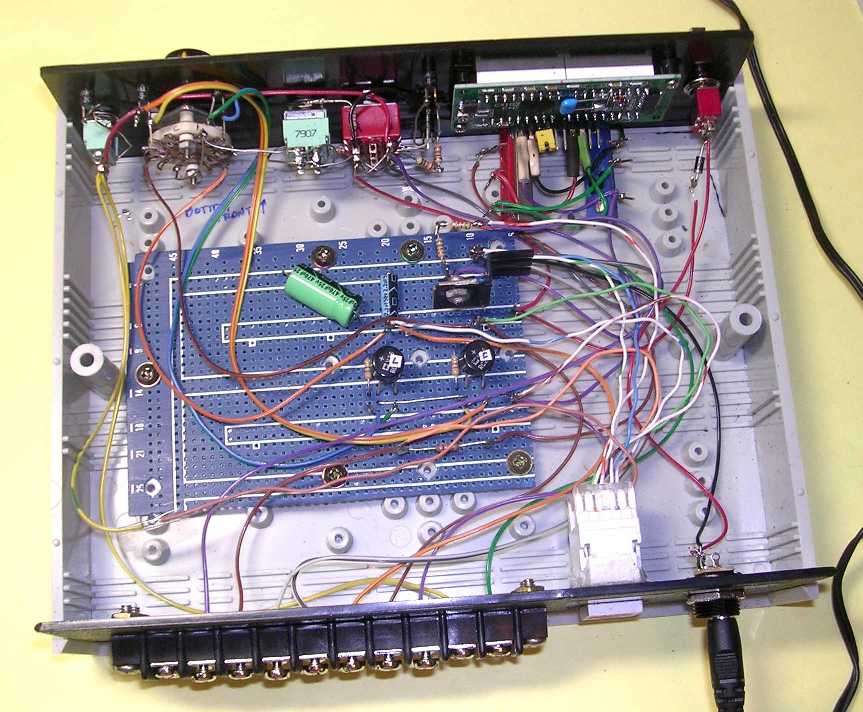
Most of the wiring is on the front panel; most of the other
rat nest wiring is just interconnecting leads from the front panel, rear terminal
strip, and rear CAT5 jack. I was originally going to use the rear terminal strip
to connect to the remote but since I decided to use CAT5 cable I added the CAT5
jack as an after thought.
The case is from Jameco, their #18869.
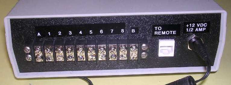
Only a 12-15 volt DC power pack at 1/2 amp is enough to
power everything (now only 1/4 amp with later mods). The terminal strip terminals
and the CAT5 jack are in parallel. A CAT5 cable is used to connect to the
remote components.
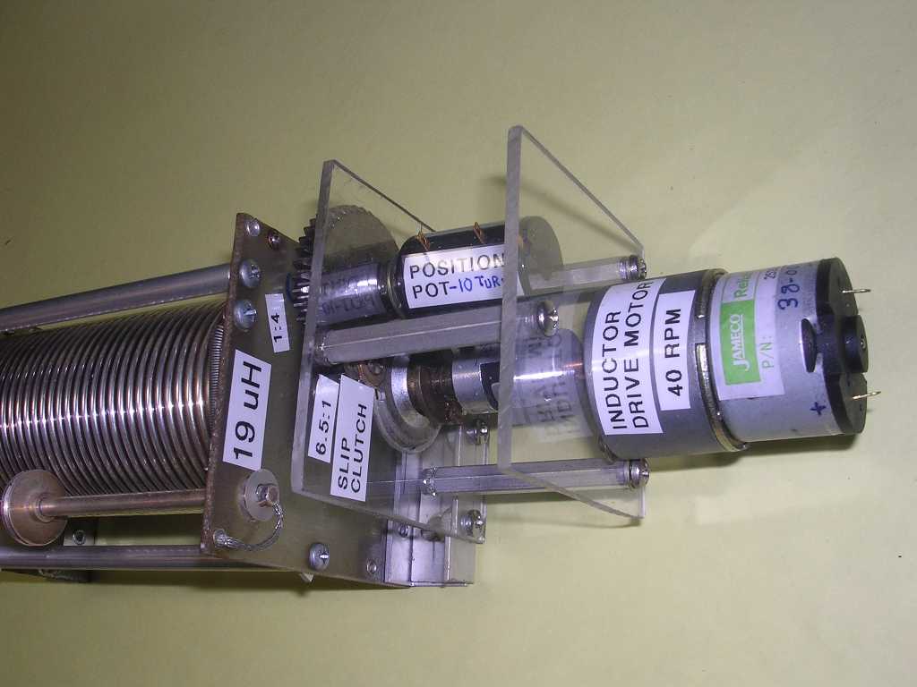
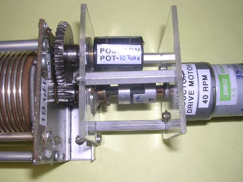
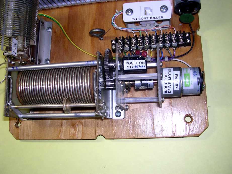
VARIABLE INDUCTOR ASSEMBLY:
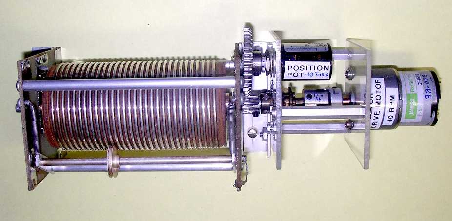
A lot of effort was used to keep the overall length of this
assembly to under 11 inches.
The variable inductor is a Tentec product #81-040, 19 uH,
30 turns.
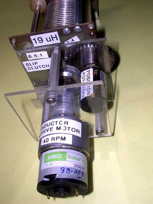
The variable inductor drive motor is from Jameco, their
#253518 (38-008). It runs at 40 RPM with 12 volts. It has a 6 mm output shaft
which goes thru a 6 mm to 1/4 inch coupler made from Jameco parts (#161998,
162270, and 162000). The #161998, a 0.197 inch hub, is drilled out to 6 mm.
The coupler goes to a Jackson Brothers type 4511 DAF ball
drive 6:1 reducer (actually about 6.5:1). This reducer is modified to provide
a slip clutch action which limits the amount of torque it passes before it stops
turning the output shaft. Prying open the 6 assembly tabs on its output side
VERY SLIGHTLY will decrease the amount of pressure on a spring washer within
it. Opening the assembly tabs too much will cause the input shaft to turn without
the output shaft turning.
When the variable inductor reaches an end stop the inductor
will stop turning but the reducer should just keep spinning only its input shaft
as long as the motor is turning. Without this slip clutch arrangement the assembly
would probably break something trying to keep turning the inductor. The motor
has a lot more torque than the inductor needs to turn it.
The reducer drives the variable inductor shaft which also
has on it a 10-tooth pinion gear which drives a 40-tooth spur gear providing
a 1:4 gear ratio. The spur gear is connected to a ten-turn potientiometer used
to provide inductor position information to the digital meter. The 10-turn pot
turns 7-1/2 turns when the variable inductor turns through its 30 turns leaving
a 1-1/4 turn cushion at each end of its rotation.
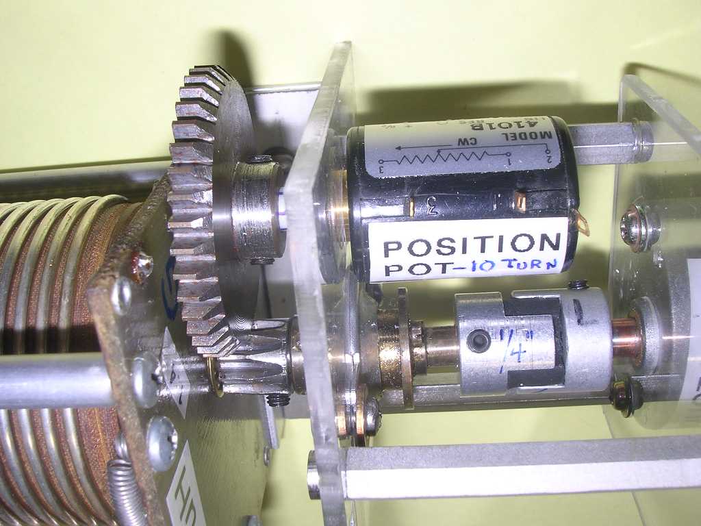
Close up of the 6 mm to 1/4 inch coupler, Jackson Bros reducer,
10 and 40 tooth gears, and position potientiometer.
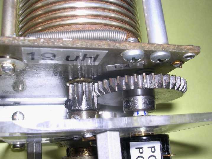
Another view of the 1:4 gear set. I would have preferred
a gear set of thermoplastic material with 1/4 inch hubs but could not locate
anything reasonably priced so I had to settle for steel. They are from a place
called Technobots Ltd located in the United Kingdom. I recall I had to drill
out the bores from a metric size to the required 1/4 inch.
VARIABLE CAPACITOR ASSEMBLY:
The differential capacitor is a MFJ 282-2015 product. I
had to remove the provided mounting brackets and make my own mounting feet off
to its side at the rear or it wouldn't fit into the 12 inch junction box. The
capacitor was also slightly 'twisted' so I only provided 3-point mounting.
The drive motor is from Jameco, their #253534 (38-010) which
runs at 24 RPM.
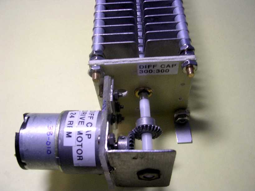
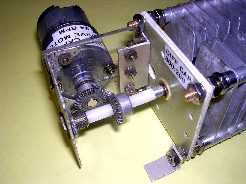
I don't know where the bevel gears came from. I had some
in my junque box and they enabled the drive motor to be mounted sideways and
make it fit within my space limitation. A 1/4 inch panel bushing is used to
support the free end of the shaft. I checked with MFJ and that plastic to metal
shaft junction is a 'threaded' connection. I was interested in how well it would
hold up.
The bevel gears might be from an R-390A receiver antenna
trimmer control. I don't have a receiver anymore to verify this.
FIXED INDUCTOR ASSEMBLY:
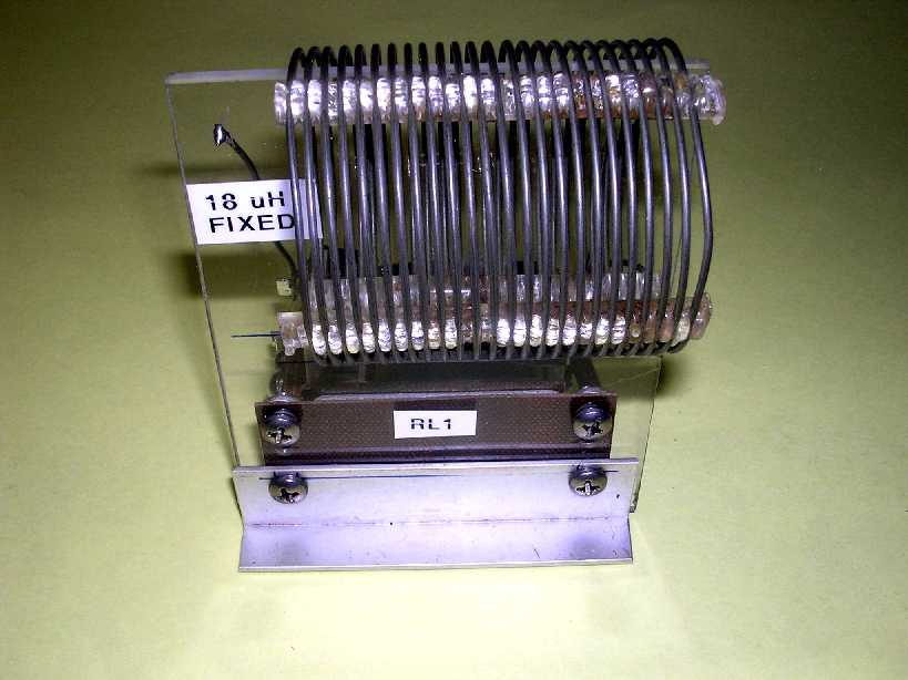
The fixed inductor assembly consists of a 18 uH fixed
coil kept shorted by the relay's Normally Closed contacts. When the relay
is energized by the +L switch on the controller, the contacts open up and
place the inductor in the circuit.
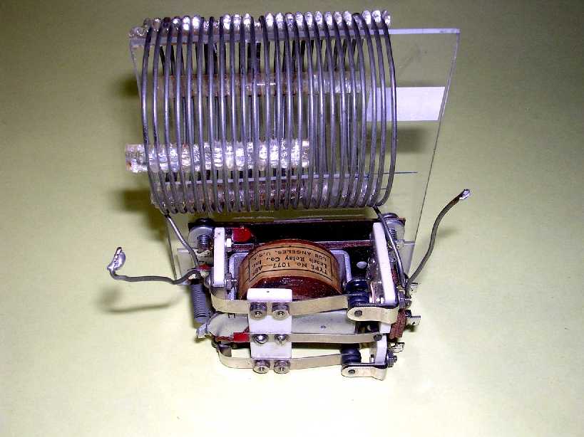
The other-side view showing the relay more clearly. The
relay is a Leach product from out of the junque box.
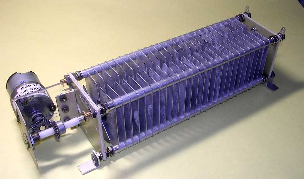
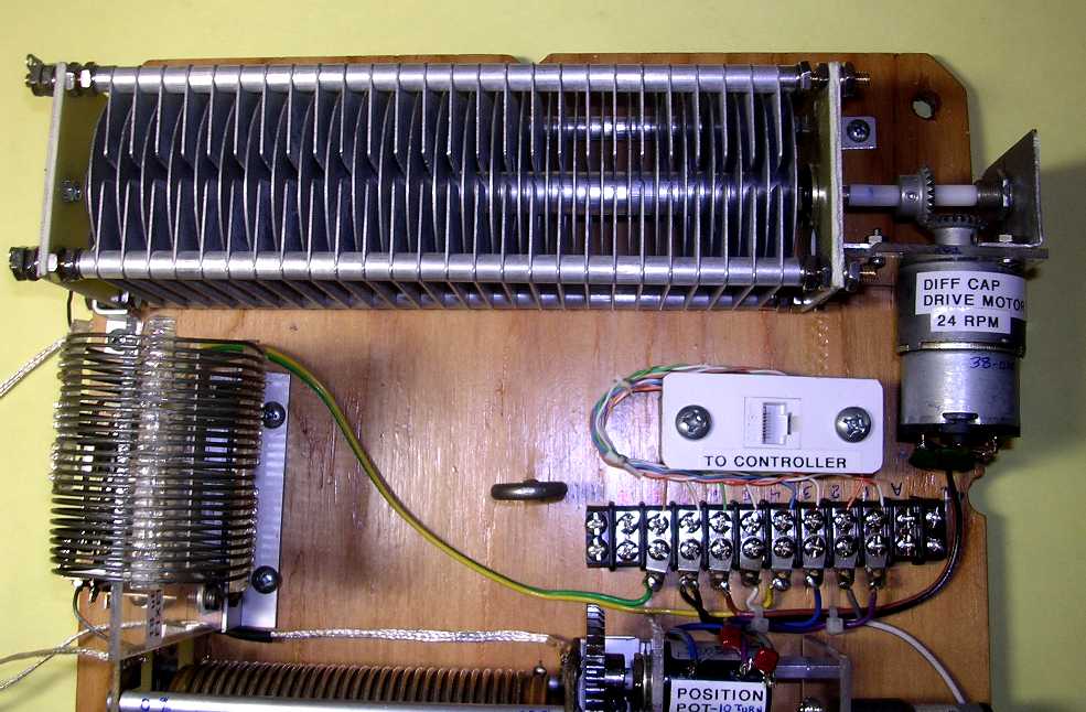
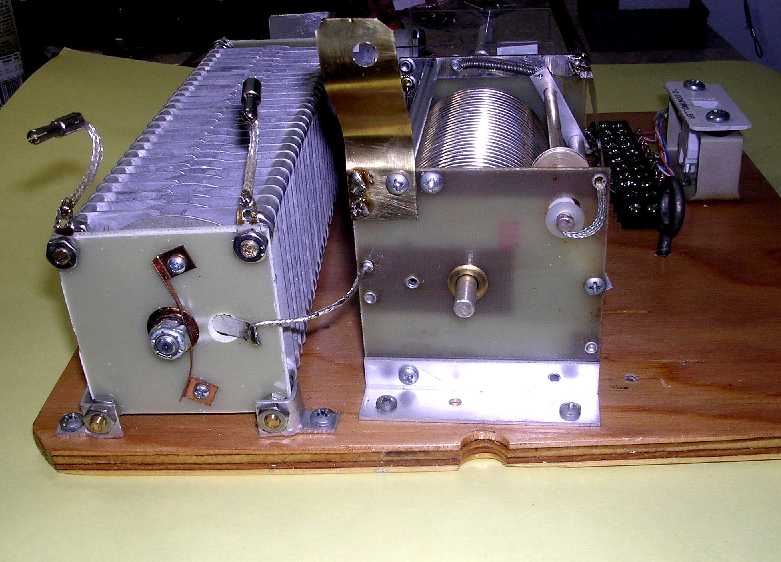
REMOTE COMPONENTS ASSEMBLY:
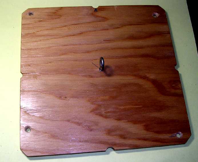
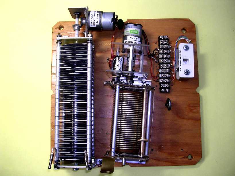
Everything in the remote unit is mounted to this piece of
1/2 inch plywood coated with several layers of polyurethane. The eyebolt lets
me hold the assembly without grabbing the components.
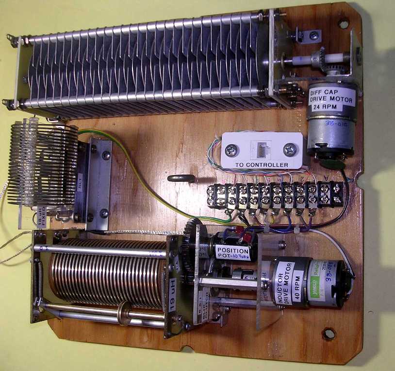
The major assemblies fitted to the board along with a terminal
strip and CAT5 jack.
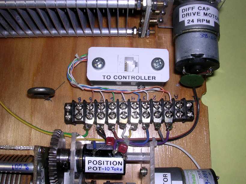
Close up of the terminal strip area.
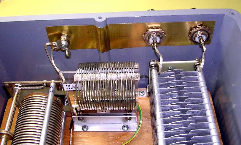
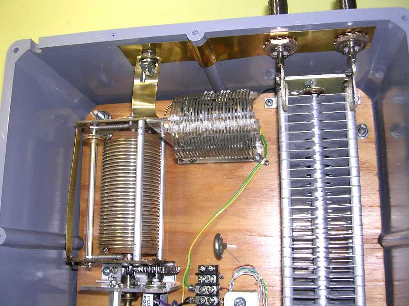
The fixed inductor connected between the differential capacitor
rotor and variable inductor.
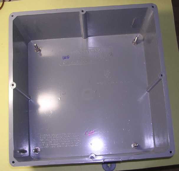
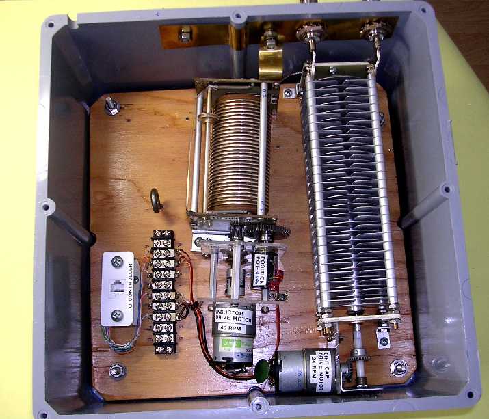
12 inch x 12 inch x 6 inch plastic junction box used to
hold the remote items. 1/4 inch stainless mounting bolts for the board shown.
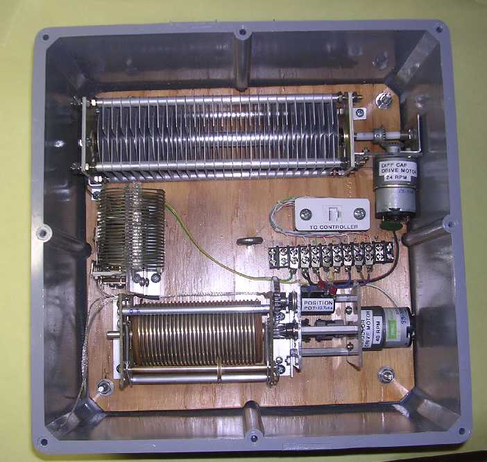
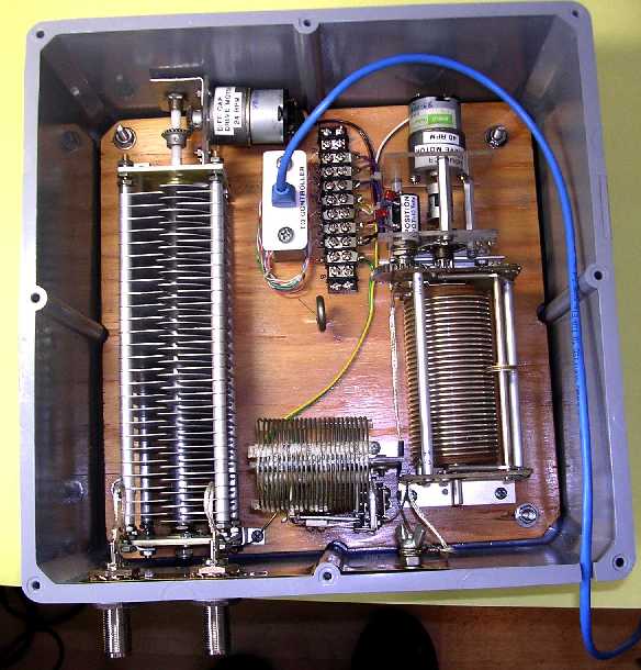
Mounting board with remote components shown in the junction
box. Note the differential capacitor just makes it! This drive motor mounting
position was actually the third position I did. The end and other side positions
obviously wouldn't have worked. The mechanical arranging and re-arranging took
a LOT of time before things worked out.
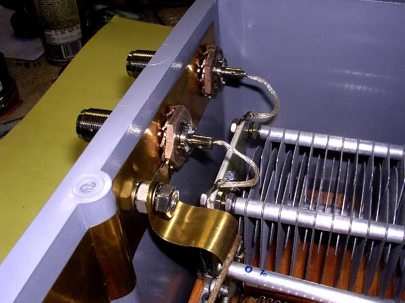
Brass plate connecting the input and output connector grounds
with the variable inductor grounds. This remote was designed to be able to remove
the board assembly without unsoldering wiring, just by disconnecting mechanical
connections. The differential capacitor has bananna plugs on its leads which
plug into the barrel coax connectors. The variable inductor has lugs connected
to a bolt under the thumbscrew. I have been thinking about changing the inductor
grounds from that braided wire to some flat brass or copper shim stock.
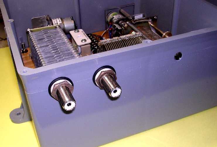
Outside view of the input and output coax connectors. Rubber
seals are used.
Connectors are Amphenol 83-1F, also known as UG-363/U barrel,
2-inch length.
Since the circuit is symmetrical with respect to the differential
capacitor either connector can be used as the input or output.
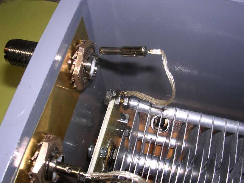
Bananna plug connected to one of the differential capacitor
stator plates. This is plugged into the center of the coax barrel connector.
CAT5 cable fitted to the junction box prior to putting the
cover on. The cable will be wrapped with some rubber tape where it passes thru
the junction box to provide a seal. The CAT5 cable proved totally adequate to
power the remote components, even with a 100 ft length. The motors only draw
about 75-80 milliamperes each and the +L relay only requires about 180 mA. The
motors still run with as low as 5 volts to them.
Well, I finally did change those variable inductor braided
ground wires to a brass strip. I think it'll work out better. There are stainless
steel star washers against the brass strip all over to insure a good connection.
Now making preps to install it under the roof eave.
How did it work?
The installation was completed, the remote input was fed
with about 105 ft of RG-213. The output of the remote went to my 1:9 balun thru
3 ft of RG-213. The balanced output of the balun went straight up to the dipole
thru about 22 ft of 600 open feed line.
Testing was accomplished with my MFJ-259B SWR Analyzer at
the input end of the long coax.
I was able to achieve a match of a 1.1-1.2 SWR from 1.8
MHz up to 27.2 MHz on all ham bands. The additional fixed inductor was only
required on 160 meters with about 90% of the variable inductor. 80 meters required
only about half of the variable inductor. At 27.2 MHz I had the variable inductor
at 0%. This told me I had too much inductance in the lead lengths to achieve
any matching on 10 meters.
So now what?
I found it interesting that I was able to achieve a match
on 160 meters with such a short antenna but since I don't plan to operate on
that band, I'm going to try eliminating the fixed inductor assembly. Then relocate
the variable inductor assembly right next to the differential capacitor assembly
and connect the two with a much shorter lead. This should also bring the variable
inductor ground strap closer to the connector grounds. The terminal strip and
CAT5 connector will also be relocated. Stay tuned for phase 2.
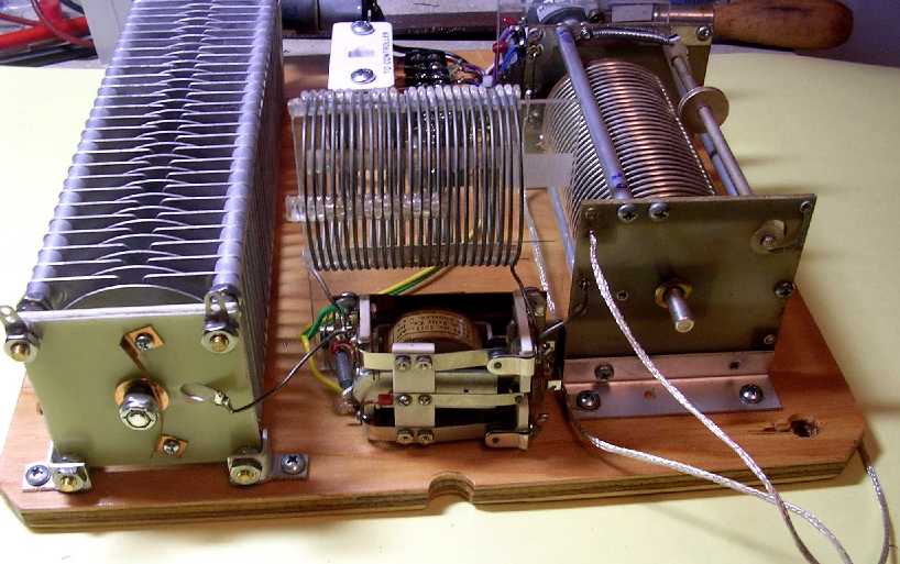
Phase 2:
Here's the reworked remote tuner with the fixed inductor
removed and the variable inductor slid over next to the differential capacitor.
Of course the +L switch on the controller doesn't do anything
now.
End-on view showing the shorter interconnect wire between
the differential capacitor and variable inductor. Even the ground strap on the
inductor was shortened by about 3/4 inch.
Reworked remote tuner mounted in the junction box.

Ground connections in the reworked remote tuner.
Closeup of the input, output, and ground area. The leads
going to the stators of the differential capacitor were also shortened by about
1 inch.
How did the modifications work?
After reinstalling the unit under the roof eave and using
the same test setup as previously done, test results turned out good!
The tuner was able to match the 88 foot dipole down to a
1.1 SWR from about 2.6 MHz to 27 MHz and 1.2 SWR from 27 MHz to 30.4 MHz. This
includes all ham bands from 80 meters thru 10 meters.
So, by eliminating the fixed inductor I traded 160 meter
matching for 10 meter coverage.
Block diagram for 80 thru 10 meter final version of the
remote antenna tuner.

The tuner installation outside.
The coax fittings were all taped up.
Common mode chokes: I attached 6 snap-on split bead 43 mix
ferrite cores onto the input coax just before the coax connector. I'm not sure
I needed that many...
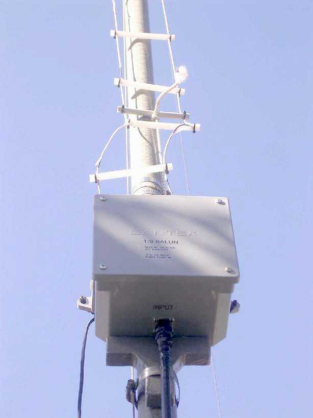
View of the 1:9 balun and 600 ohm open feed line.
Details of the balun are in my 'technical stuffs' area.


For sources on some of those hard-to-find mechanical items
I used, click HERE.

