
| HOME |
RADIO |
THE BIG STORM |
CONTACT ME |
MY BANJO |
FAVORITES |
NC SCUBA |
PROJECTS |
    |
|||
 |
|||
| The
dipole antenna is the most widely used type of
antenna for high frequencies and in physics theory, is the simplest
form of antenna. A one-half wavelength dipole antenna commonly
consists of two quarter-wavelength pieces of copper wire, called
"legs", placed end to end, then trimmed to the resonant center
frequency of the desired band. The feedline shield and center
conductors are then connected to a leg. In a dipole antenna
design, the highest voltage is found at the center end of each dipole
leg whilst the lowest voltage is found at each furthest end of the
dipole leg. Thus, the highest resistance is found at each
furthest end of each dipole leg whilst the lowest resistance is found
at the center of the dipole leg. The transmitter cycles
alternating current through each leg of the dipole, and each leg is
always the inverse polarity of it's counterpart. Instantaneously,
the dipole is charged negatively on one leg, beginning at zero and
rising to a maximum charge proportional to the power supplied by the
transmitter; then the charge decreases to zero. That leg of the
dipole becomes charged positively on the next half-cycle of the
existing waveform. This process creates a rising and falling electric
field from one leg of the dipole to the other, which moves away from
the antenna. Similarly, the current in the dipole establishes a
magnetic field encircling the dipole, which also moves away from the
antenna. The electric and magnetic fields together form the
radiated electromagnetic field, which is the "radio signal" that is
heard by the receiving antenna. In an ideal dipole antenna
design, identical current will exist on each leg of the dipole.
Any type of conductive metal wire can be used to make the legs of a
dipole; copper being the best conductor whilst steel being the most
durable conductor. Copper is a soft metal and tends to stretch,
causing the dipole leg to snap in high winds, yet steel is a poorer
conductor and is susceptible to corrosion. So, oftentimes, copper
coated steel wire is preferred as a trade off between superior
conductivity VS strength. A German physicist named Heinrich Hertz first demonstrated the concept of the dipole antenna in 1887, and an Italian inventor named Gugliemo Marconi perfected the design. Marconi was able to design dipole antennae in the early 20th century to achieve long-distance radio communications from ships at sea. At that time, telegraph was the main means of long-distance communication, but it required stations to be connected by wires. Many lighthouses and certainly ships at sea couldn't be connected together by a cable, so Marconni set out in 1897 to invent a wireless communication system. By 1910, Marconi had equipped most passenger ships operating in the Atlantic with his wireless radio. Marconi's wireless transmitted about 300 miles during the day and about 800 - 1,000 miles at night due to the refraction of the radio waves in the Earth's ionosphere. Titanic was outfitted with the best wireless equipment Marconi had to offer, and her multi-wire "T" dipole antenna was over 150 feet in height, ran nearly 400 feet in length between Titanics fore and aft smokestacks, and was made of #18 B&S uninsulated silicon bronze wire. I have talked to other hams in Italy, Germany, Germany, Japan, the Caribbean, and Ireland with my home made 20-meter dipole HF antenna. |
|||
 |
|||
| The 15 meter band is
either awesome or dead, depending on sunspot solar
activity. The 15-meter amateur band wavelength reflects off the F2 layer of the earths ionosphere. Thus this band is great for world-wide communication during daylight hours. The 15 meter amateur band is more influenced by solar cycles than the 20-meter band. While there is much less night time activity on the 15-meter band, at the peak of the sunspot cycle it can provide awesome around-the-world communications. On the other hand, during the bottom of the solar cycle, the 15-meter band may be closed for days at a time. The good news about the 15-meter amateur band is that you don't need a seperate antenna. Since 21,000 Hertz is a third harmonic of 7,000 Hertz (7,000 x 3 = 21,000), an antenna that is resonant on the 40-meter band will also be resonate on the 15-meter band. So roll the dice and try your luck. |
|||
 |
|||
| Just
about all of the
serious DXers hang out on 20 meters! This can be a very exciting band with some of the best DX found on any band. Around the world daytime communications are generally possible and when the sunspot cycle is peaking. The 20-meter band can be used around the clock! Not likely to be used for short-range communications, the only way to work someone a few hundred miles away would be scatter or possibly "long path". Ground wave signals of about 50-75 miles might be all you would expect. At the bottom of the sunspot cycle, openings to other continents are short, rare and few and far between! I built my 20-meter pertable fold-up dipole HF antenna from 12-gauge stranded copper wire and black Starboard Polyethylene sheet. I trimmed my 20-meter dipole to 14.280 MHz and achieved a 1.5 SWR. 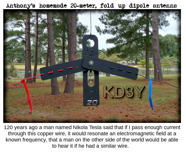   |
|||
 |
|||
| This
is many ham's favorite band because it is always open somewhere. During the summer daytime distances of 300-400 miles and night time distances of 1000 miles are very common. Winter days with 500 miles or more are usual and night time conditions bring intercontinental communications. The 40-meter band is not as affected by the sunspot cycle as the 20 and 10-meter bands are. Many nets frequent 40-meters both day and night.  |
|||
 Ideal for POTA! I built this multi-band dipole from 12-gauge copper wire. It can be mounted on a mast with U-bolts or suspended from a tree limb. The top dipole (black wire) is aproximately 65 feet long and tuned to the 40-meter band, which natutally is also resonant on the fifteen-meter band. The bottom dipole (red wire) is aproximately 34 feet long and tuned to the 20-meter band. The connections are inside a waterproof PVC box, the coax connection is protected from the elements by a rain guard, and all the fasteners and hardware are stainless except for the dipole leg insulators. This dipole can be used in the horizontal configuration for long-distance skywave propogation or suspended lower to the ground in the inverted "V" configuration for shorter distance NVIS propogation.     My dipole antenna plans were published in the Pamlico Amateur Radio Club Newsletter. Download my fan dipole antenna and white paper here.
|
|||
 |
|||
| Ideal
for local communication with family & friends I built my GMRS J-pole antenna from 1/2 inch copper pipe. Mounted on a mast, using a SMA to SO-239 adapter, it vastly out performs the "rubber duck" on the handheld radio. It can be mounted on a mast or hung from a tree by a non-conductive rope.   The Crystal Coast GMRS net Each Monday at 2000 hrs EST  |
|||
| |


Last Updated 02-15-2026