| ADVANCED LESSON 73 |  |
| LEARNING OBJECTIVES and NOTES | |
| Measurements - R.F. Power measurements | |
|
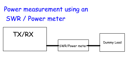
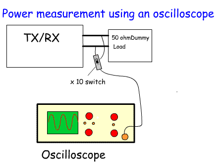
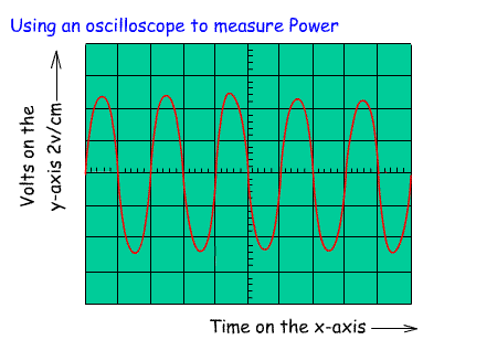
10d.1 Understand that steady RF power may be determined by measuring the RF potential difference across a dummy load. There are several ways to measure the power output from a transmitter transmitting a steady, unmodulated signal. i.e the signal output when you hold down the key. You could use one of the modern SWR meters which is calibrated in watts. It is important in all power measurement to measure the power into a 50 ohm dummy load. So, set up the rig, connect it to an SWR /power meter, connect the SWR antenna side to a 50 ohm dummy load. Adjust the SWR range to match that of the transmitter estimated output and make sure the dummy load is designed to handle the power. One of the limitations with this method is not knowing how accurately the SWR/power meter is calibrated. An improved method is to connect the output from the transmitter to a 50 ohm dummy load and then to measure the potential difference across the dummy load using either an oscilloscope or diode probe. Using an oscilloscope and the 10x probe turn on the transmitter and measure the peak to peak voltage. The voltage root mean square = 0.353 x Vp-p. The average power Pav = (Vrms)2 / R Example 1 If the oscilloscope reads 10V p-p with a 10x probe, Vp-p = 10 x 10 = 100V Vrms = 0.3535 x 100 = 35.35V Pav = (35.35)2 /50 = 25W If you do not possess an oscilloscope a diode probe can be used instead with a digital multimeter to measure the voltage. The probe has a diode which acts as a half wave rectifier. The voltage after the diode is equal to the peak value of the rectified wave minus the barrier voltage of the diode. If an OA91 germanium diode can be found the voltage drop will be about 0.25V. The actual peak voltage will be the peak output voltage after the diode + 0.25V. |
    |
| Understand the meaning of PEP (peak envelope power) of an SSB
transmission and that it may be determined using a peak reading power
meter or an oscilloscope and dummy load. When we use SSB the voltage shown by an oscilloscope will vary depending on how loud we speak and the way we speak. This makes it harder to work out the power. What we normally do is to measure the peak to peak voltage across a 50 ohm resistor using an oscilloscope and a two tone oscillator in place of the microphone. The two tones must be of the same amplitude and not harmonically related.Then calculate the peak envelope power using this equation: Example 1 If the PEV = 100V and the resistance = 50 ohms PEP = (100 x 0.707)2 / 50 =99.97 Watts (we can say 100Watts) To set up an oscilloscope to make sure our speech does not take the power to more than 100W, mark the highest and lowest peak on the oscilloscope with a china graph pencil. Replace the two tone oscillator with the microphone and set the microphone level so that the peaks of your speech do not exceed the marks on the screen. You now know that your pep output power is 100W. You could repeat the experiment with a two tone signal and power out that gives a p-p voltage of 200V. PEP = (200 x 0.707)2 / 50 = 399.88 Watts (We can say 400W) Again mark the peaks with a china graph pencil. Replace the two tone oscillator with a microphone and adjust the microphone level and power out so that speech peaks do not exceed the 400W marks. In the UK on most bands this the maximum power allowed! If you do not have an oscilloscope use a peak reading power meter. These usually have a capacitor across the meter that holds the reading at the highest power. |
 |