
| ADVANCED LESSON 34 | |
| LEARNING OBJECTIVES and NOTES | |
| Transmitter architecture |
|
|
4a.1 Understand the block diagram of an SSB transmitter employing mixers to generate the final frequency. In the Intermediate examination you looked at the block diagram of several transmitters - CW, AM, SSB and FM. At advanced level you need to understand the block diagram of an SSB transmitter that uses a mixer to generate a final frequency. On the block diagram opposite the audio from the microphone is amplified by the AF amplifier. This is then mixed with a crystal controlled RF oscillator in a balanced modulator to create an IF frequency. For example a 9MHz crystal controlled RF oscillator. This produces a double sideband signal at 9MHz. The sideband filter strips out one sideband leaving a single sideband of about 9MHz signal. There is then an IF stage that will amplify the 9MHz IF This is then mixed with the synthesiser that will mix with the 9MHz to produce the required the desired amateur band For example a frequency of 11 to 11.5 would mix with 9 MHz to produce an output of 1.5 to 2.0MHz and 20 to 20.5 MHZ. A filter after the mixer would select the 1.5 to 2.0MHz signal. |
 |
|
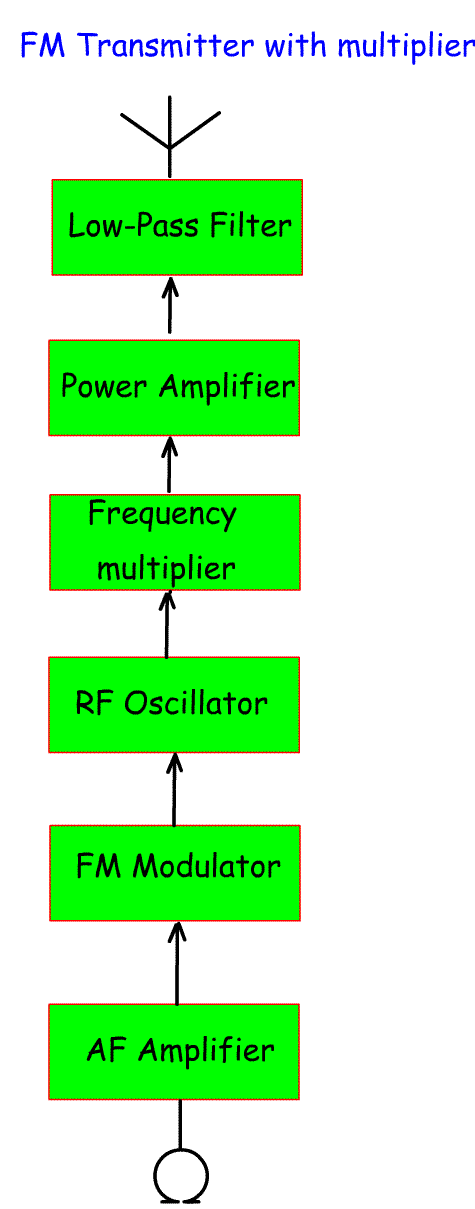
Understand the block diagram of an FM transmitter employing either
frequency multipliers or mixers to generate the final frequency. The FM modulator shifts the RF oscillator from side to side to produce an FM signal. This is carried out at a lower frequency than the output frequency - for example 1/5 of the frequency. So for an FM signal on 145.500 a signal would be generated on 145.500/5 = 45.5 MHz. This then goes through a multiplier that selects the fifth harmonic (x5). This then passes to a PA and Low-pass filter. If modulation takes place at the lower frequency, then the deviation will also be multiplied. So, in the above example to achieve a 2.5kHz deviation at 145.500, the deviation at 45.5 would be 2.5 / 5 = 0.5kHz An alternative is to mix the FM output from the RF oscillator with an oscillator on a frequency that results in the appropriate output. So taking our example above the FM signal generated at 45.5MHz could be mixed with 100MHz oscillator to produce 100+45.5 = 145.500MHz. The multiplier method will of course multiply any drift in the 45.5 oscillator, so a drift of 1kHz at 45.5 will be a drift of 5kHz at 145.500. With the mixer solution and assuming the 100MHz signal is derived from a crystal oscillator a 1kHz drift at 45.5 will still be 1kHz drift at 145.500. In terms of modulation, the FM deviation required will be applied to the 45.5 MHz oscillator. So for a 2.5 kHz deviation, 2.5 kHz deviation will be applied to the 45.5 MHz oscillator. |
 |