| ADVANCED LESSON 31 |  |
| LEARNING OBJECTIVES and NOTES | |
| Solid state devices 5 | |
|
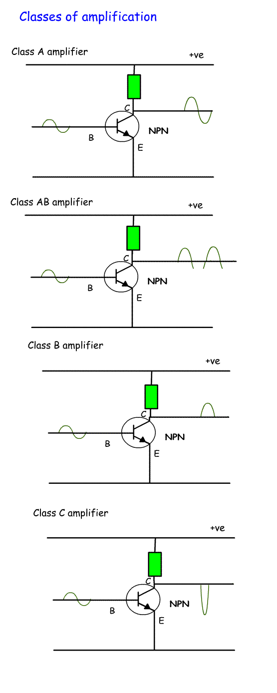
3n.7 Recall the characteristics and typical circuit diagrams of different classes of amplifiers (i.e. A, B, A/B and C). When transistors are used as amplifiers it is important to take into account the type of amplifier required. The classes of amplifier are called A, B, A/B and C. There are D and E classes, but we don't need to bother about those! The class of amplifier is determined by the bias setting on the base. Class A amplifier The bias is set so that the amplification is linear. This means that the output is an exact copy of the input - but with a greater amplitude (height). Conduction angle = 360o (i.e. amplification occurs throughout the cycle) Linear amplifiers are used for AM (generated at a low level) and SSB. They have a lower level of harmonics and IMD. They are not very efficient. They have a high gain because they amplify both the positive and negative going parts of a sine wave. Class AB amplifier This is biased so that it amplifies more than half the cycle, but not the whole cycle. It gives more linearity and gain than class B, but not as much as class A. Conduction angle is between 180o and 360o Class B amplifier The bias is set so that amplification only takes place for half the cycle - either positive going or negative going.. This means that the output is a copy of either the positive or negative half of the cycle - but with a greater amplitude (height). Conduction angle = 180o (i.e. amplification occurs only for half the cycle) A Class B amplifier is more efficient than class A, but contains a higher level of harmonic distortion which must be filtered out. By using 2 transistors together in what is called push-pull, one can have its bias adjusted to amplify the positive going side and the other the negative going side. The two are then combined at the output to recreate the full wave. Push-pull amplifiers cancel out even harmonics. If a single transistor is used in Class B then a resonant circuit must follow the output. This effectively adds the missing half of the wave. Class B amplifiers have less gain than Class A. Class C amplifier This is biased so that it conducts for less than 50% of the time. The conduction angle is < 180o (< means less than). These have worse linearity than Class A and B. They are very efficient They have low average output power but need high input power. They are use for modes such as FM, CW, or RTTY. |
 |
3n.8 Understand the concept of the efficiency of an amplifier stage and be able to estimate expected RF output power for a given DC input power, given the stage’s efficiency. The efficiency of different classes of amplifier vary. Efficiency is = (power out / power in) x 100 E.g. if an amplifier draws 90 watts and has an RF output of 30 Watts efficiency = (30/90) x 100 = 33.3 % efficient. These are the efficiencies of some of the classes of amplifiers. Class A = 50% Class B = 78.5% Class AB = 50-78.5% Class C= 85% If a transistor is only 50% efficient, then the other 50% will be given off as heat. This means that a class A amplifier will need a bigger heat sink because 50% of the power is produced as heat. A class C amplifier only produces 15% heat, so requires a smaller heat sink. |
Example 1
Example 2
|