| ADVANCED LESSON 30 |  |
| LEARNING OBJECTIVES and NOTES | |
| Solid state devices 4 | |
|
3n.6 Identify different types of small signal amplifiers (e.g. common
emitter (source), emitter follower and common base) and explain their
operation in terms of input and output impedances, current gain,
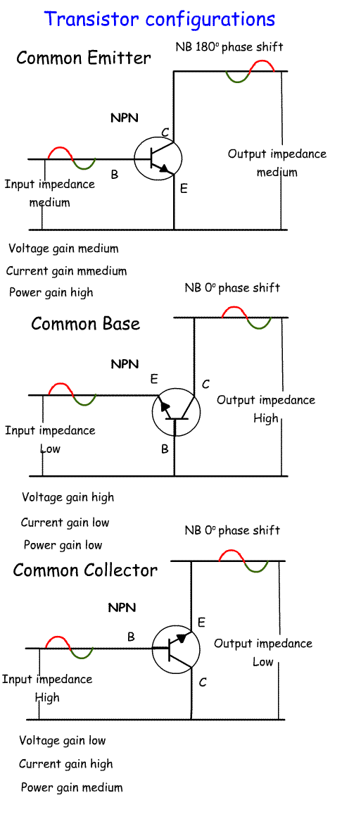
voltage gain and phase change. The transistor circuits looked at so far have all being configured with a common emitter. i.e. the input is between the base and emitter and the output between the collector and the emitter. There are other ways of connecting up a transistor to form amplifiers for small signals. These will have an effect on the input and output impedances, the current gain, the voltage gain and phase changes. The three configurations we will look at are: Common emitter Common base Common collector (Emitter follower) We will look at these for an NPN transistor. To make life easier we have taken out the resistors from the drawings. Common emitter This is a high current amplifier. To make it a voltage amplifier then a load resistor or a tuned circuit is placed between the positive line and the collector. The voltage is taken off the collector via a capacitor. The common emitter is the most common configuration. Common base The gain is 1 or less meaning that the common base configuration often acts as an attenuator. It is used in microphone pre-amp circuits and RF amplifiers, where the earthed base acts as a screen between the input and output. It can be used to match a low impedance to a high impedance Common Collector ( Emitter Follower) Voltage gain low or even zero Widely used as a buffer amplifier for example following an oscillator where its high impedance prevents pulling of the oscillator frequency. Also used an impedance matching device. |
 |