DF0WD/DL4YHF's Longwave Stationlast updated: December 10th, 2000 |
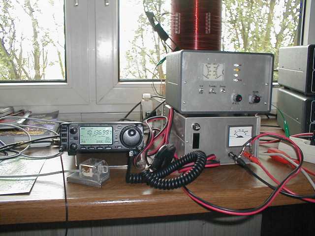
| The main equipment for 136kHz is a linear(!) transverter
with a maximum output of 100 watts (to compensate the loss in the matching
system .... ..). The transverter can be seen on the photo below in front
of the antenna coil. It converts the 136kHz-signal to 10.136MHz and vice
versa. The small Icom IC706 (old model) on the left side is almost deaf
on 136kHz, but it works fine on 10.136 as RX and (QRP-) TX. It does not even
require a good IF filter because of the transverter's preselector (we have
an extremely strong commercial signal on 138.8 kHz in Germany, which is S9+60dB
on the longwire. That signal would totally block the Mixer (and the IC706)
without its "sharp" LF-preselector.
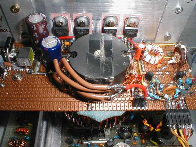
The transverter uses a 10.000Mhz-LO with a cheap crystal, a Schottky ring
mixer, a driver, and a double push-pull final amplifier with four matched
(!) IRF540 MOSFETs operated at 13 Volts DC . The final stage has an
SWR-protection using an SWR-bridge which is also used to display the SWR
(Fwd+Rev) on the front panel. This makes the PA virtually "undestructable"
by load mismatch. The output power drops below 10 watts if the load
is not purely resistive 50 Ohms. Because this is a linear transverter, the
output power can be controlled by changing the output power of the
HF-transceiver.
A PI-network is at the lower side of the final board. A part of the large Amidon T200-2 powdered-iron toroid can be seen. 50 turns of enameled wire give about 30 uH. Two Wima "FKP" capacitors (47nF each) together with the 30uH-Inductor are used in a PI-filter which also transforms 13.5 Ohms from the large pot-core-transformer into 50 Ohms for the output. The efficiency of the final stage is only about 70 percent as long as it remains a real "linear", but that doesn't hurt at the transverter's maximum output. If there will be more time, I will convert some of the circuit diagrams from my ugly hand-drawn sketches into EAGLE drawing which you may find here in future.
|