A Preselector for the LF Transverterlast updated: October 25th, 2000 |
| .
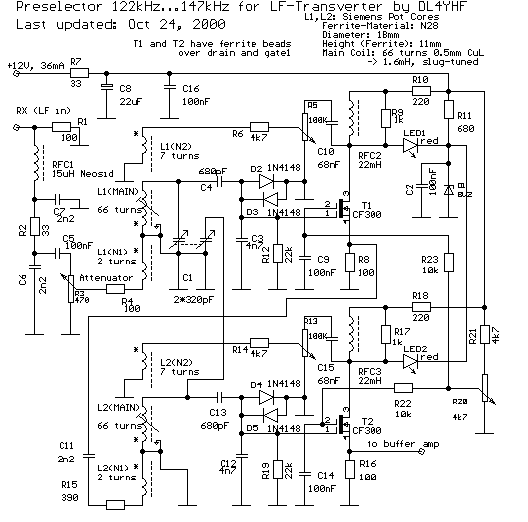
The LF-preselector described here is part of the LF-Transverter. The 136kHz signal is filtered by a very narrow 2-stage FET preselector using "Q-multiplication" (feedback to increase the Q factor like an audion stage). Its bandwidth is less than 200Hz, adjustable via 100k-trimmers. The preselector-frequency has to be adjusted by a 2-chamber variable capactor which can be found in old AM radios. This makes tuning a bit "tricky" because you have to rotate the preselector knob together with the VFO of the SW transceiver to hear anything at all.The following diagram is my second attempt for a narrow preselector (the first used BF256-JFETs instead of the CF300-GaAsFETs):
The low-pass filter at the input is assembled very close to the PL-connector. It is very important to prevent any signal around 10.137MHz from getting "further" into the converter. Otherwise you may be astonished to hear SSB stations operating on "137 kHz". The LF-signal may be attenuated with a poti on the front panel. The attenuator's output is coupled loosely to a "point of low impedance" of the first parallel resonant filter. C3 and C4 are a part of the first filter but also a voltage divider for the GasFet's gate. The "variable" part of the capacity is one half of C1. The tuning range of the prototype is 122kHz to 147kHz. The LED on the drain is used to protect the FET against too high voltages (which may otherwise occurr during oscillation or VERY strong input signals). D2/D3 (D4/D5) are required to protect the gates. The usual signal levels here are much lower than the threshold voltages of a Si-diode, so no intermodulation should be caused here. Both FET stages are used to increase the Q-factor of the parallel resonant filters. Without the FETs, each filter itself has a Q of about 200. The FETs may increase the Q's up to 2000 (just below the point of self oscillation), but setting both Qs below 2000 will reduce "ringing" of the filter. R6 and R14 are trimpots in the feedback path to adjust the Q-factors. R20 controls the gains of both stages and can be used to set the bandwidth from the transverter's front panel. If the stages do not oscillate with R6, R14 and R20 turned fully towards "low bandwidth", reverse the feedback windings (L1N1 and L2N1). Note that the source resistors (R8, R16) are not shunted by capacitors (to keep the gain and the intermod down) !
The coils (L1 and L2) are old "Siemens" pot-cores from my junk box, you can
see a description of the coils in the circuit diagram. These slug-tuned
coils had 66 turns of 0.5mm enameled copper wire whith gave them an inductance
of about 1.66mH. I added "secondary" windings (N2) for the feedback with
7 turns of thin wire and "primary" windings (N1) with 2 turns as
low-impedance taps. The value of C11 and R15 determines the coupling of both stages. You may replace these to find the best values for a "nice" filter response yourself (depending on the "Q" of your coils). You may also download the schematics as an EAGLE-file.
|
See also: Longwave - Index. |
