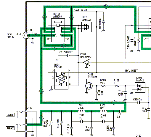
| Fig.1: IC-756Pro3 RX-ANT Input Circuit (p/o RF-B Unit) |
|---|
 |
| Note on Fig.1: When ANT1 or ANT2 is selected, Q101 base is HIGH, operating RL101 and connecting J101. Selecting ANT1/R or ANT2/R sets Q101 base LOW, releasing RL101 and connecting RANT. Excessive RF voltage applied to RANT is rectified by D101, turning on Q103 and Q104. This operates RL101, switching RX signal path from RANT to J101. Input power for switchover is approx. +10 dBm. |
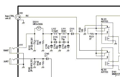
| Fig.2: IC-756Pro2 RX-ANT Input Circuit (p/o RF-A Unit) |
 |
|
Note on Fig.2: RL101 switches RX signal path between J101 (ANT 1/2) and RANT (ANT1/R, ANT2/R) as in Fig.1. Excessive RF power applied to RANT blows fuse bulb DS111. |
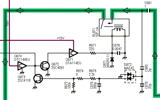
| Fig.3: IC-7800 RX-ANT Muting & Protection Circuit (p/o BPF Unit) |
 |
| Note on Fig.3: When receiving, T8V is LOW; Q874 turns Q872 and Q871 on, operating RL871 and completing RX RF signal path. When transmitting, T8V is HIGH; RL871 releases, breaking RF path. Excessive RF voltage at input is rectified by D872, turning Q873 on. This turns Q872 off, releasing RL871. Input power for switchover is approx. +10 dBm. |
|
Text copyright © 2006 A. Farson VA7OJ/AB4OJ. Images courtesy Icom Inc. |
Last updated: 06/02/2012. |