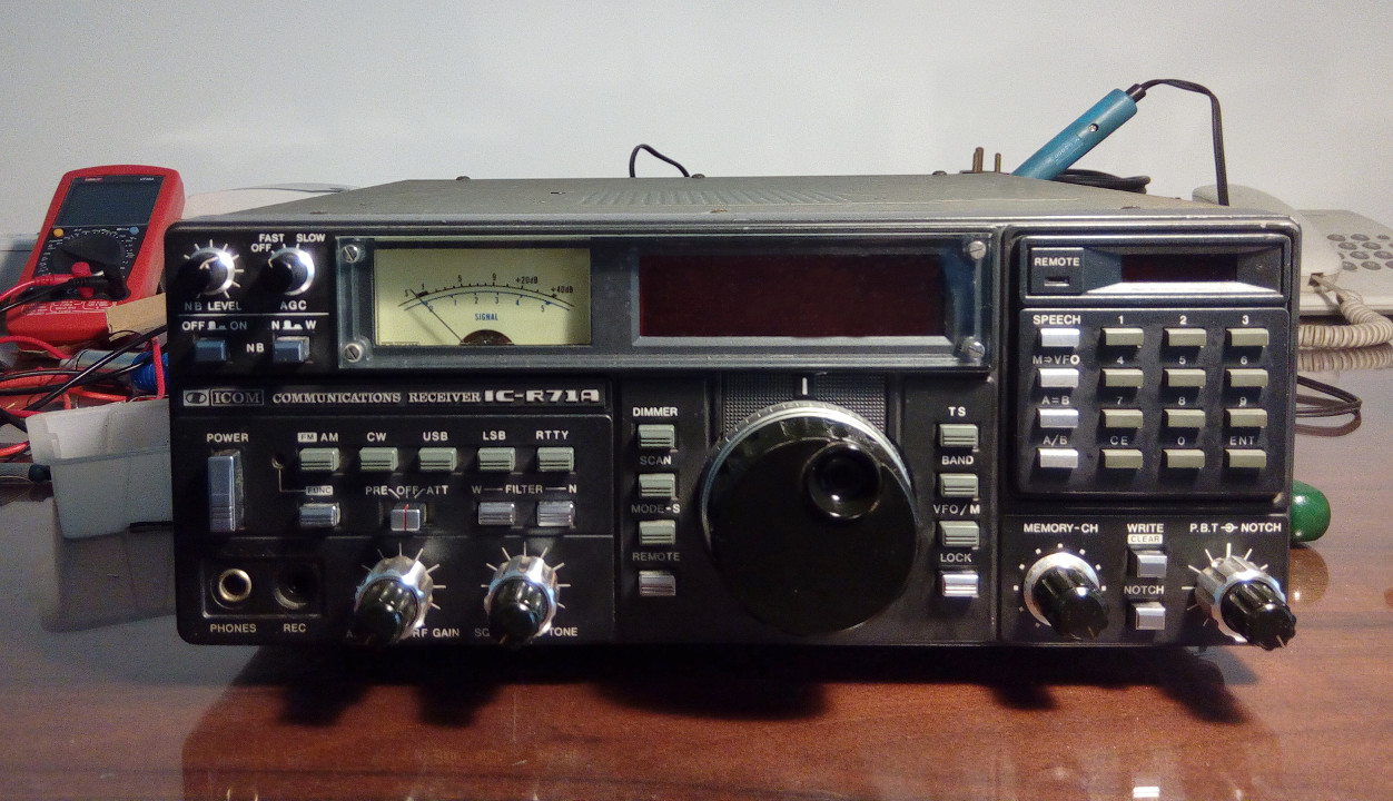
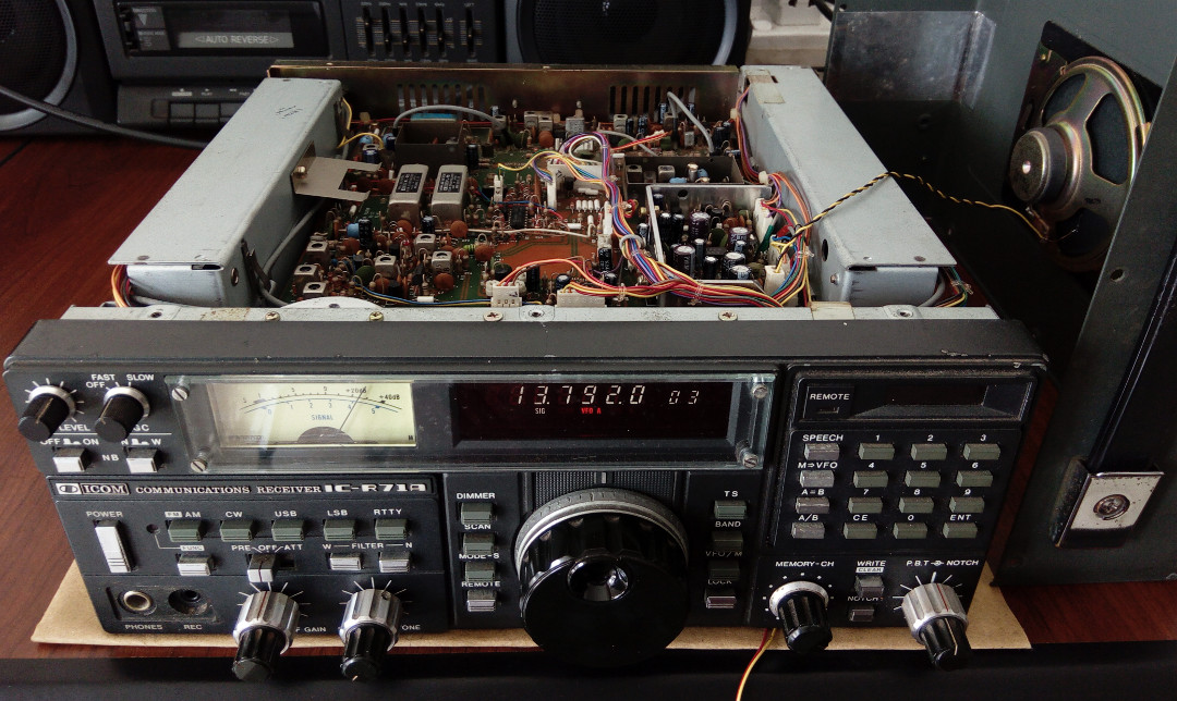
I received an ICOM IC-R71A from a friend. The IC-R71A is a multi-mode quadruple superheterodyne receiver covering 100 kHz to 30 MHz. When it arrived at my workshop it was completely dead, though the outer casing and front panel were in excellent condition.
Before troubleshooting I downloaded both the user manual and service manual. As with all ICOM products, both are exceptionally detailed.
This receiver contains many PCBs, including:
There are also slots in the chassis for optional boards such as an FM board.
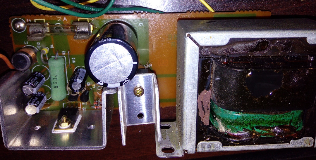
Examining the power supply board, I found dry joints on the rectifier module and the 2SD880 power transistor. Re-soldering these joints brought the PSU back to life and the receiver powered up.
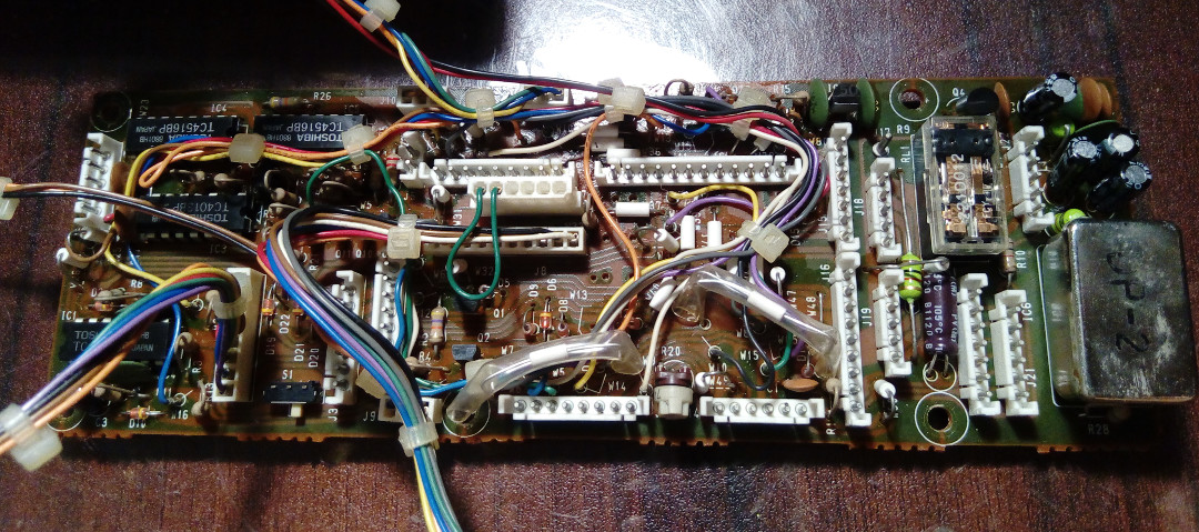
After a few minutes of operation, two faults became clear: a faulty RF gain controller and very low audio output. Further inspection revealed that most of the electrolytic capacitors, especially on the PLL board, were in very bad condition - most were leaky.
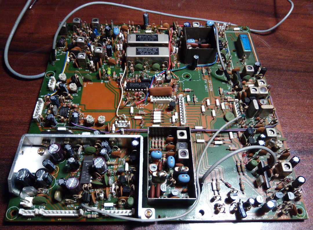
I decided to recap all electrolytic capacitors in the receiver. Sourced mostly Nichicon capacitors from the local market (approximately LKR 300 total), supplemented with Panasonic and ELNA for other values. Used 16V capacitors where 10V parts were unavailable.
The logic board contains a battery-backed DRAM module.
According to ICOM, this lithium battery retains memory content - if erased, the radio may become unusable. I took extra precautions while recapping this board. The full recap took approximately one week.
After replacing all the capacitors the receiver came back to life completely. I was genuinely impressed - compared to my other receivers, this IC-R71A performs outstandingly well and its sensitivity is remarkable.
The only remaining issue is the S-meter backlight lamp. I tried coupling a white LED in but the dimming function doesn't behave correctly with LEDs, so I'm keeping it as-is until I source a suitable filament lamp.