4S6DRJ

Eddystone EC10 Communication Receiver
Restoration & PSU Add-in

Eddystone EC10 MK1 550 kHz – 30 MHz 10× PNP Germanium Transistors

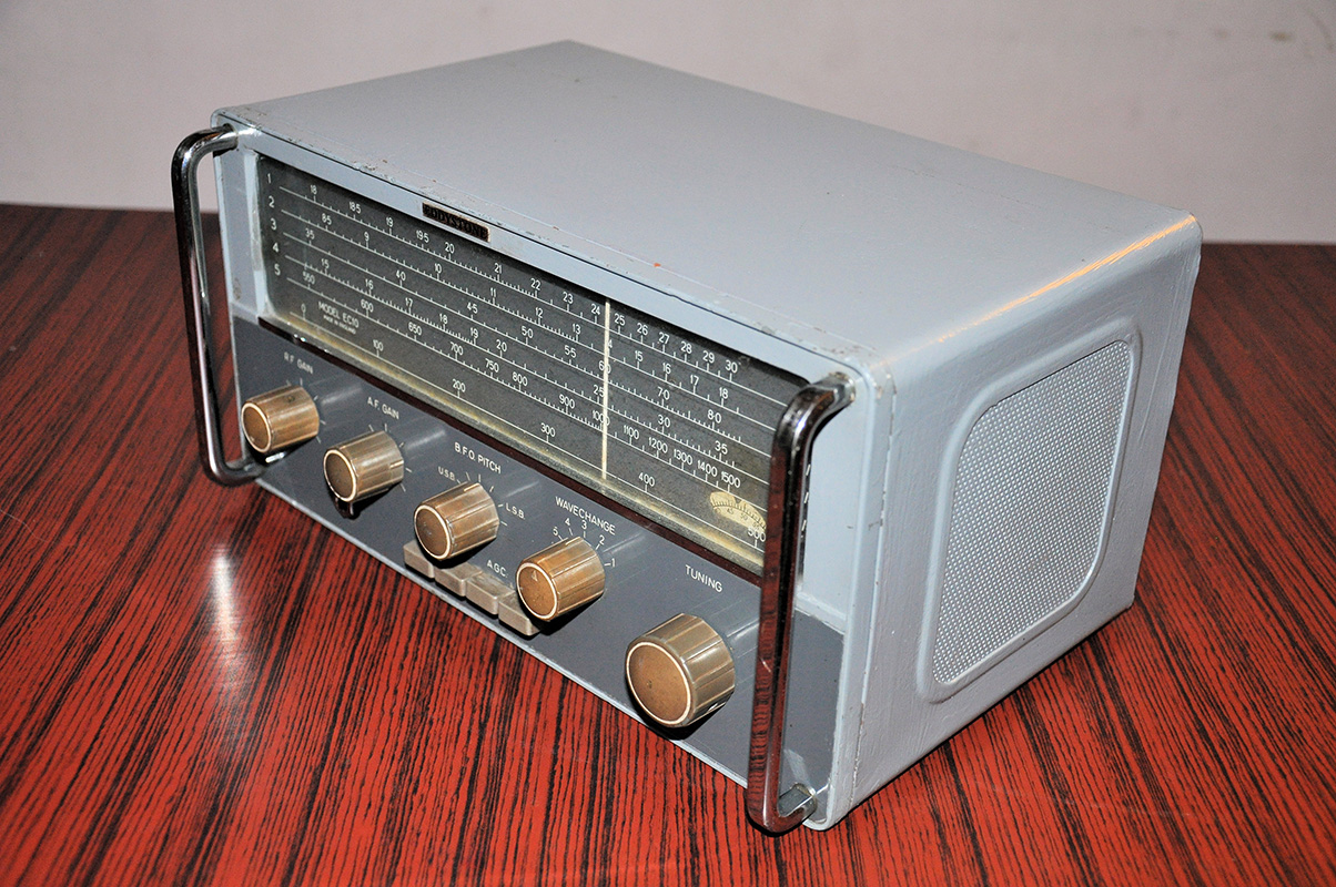
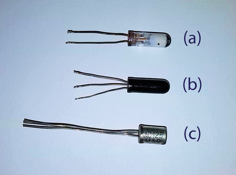
Recently I received a vintage Eddystone EC10 MK1 communication receiver from a friend - it was completely dead on arrival. The EC10 MK1 is one of Eddystone's earliest solid-state communications receivers, using 10 PNP Germanium transistors. It covers 550 kHz to 30 MHz and includes a BFO for CW and SSB reception.

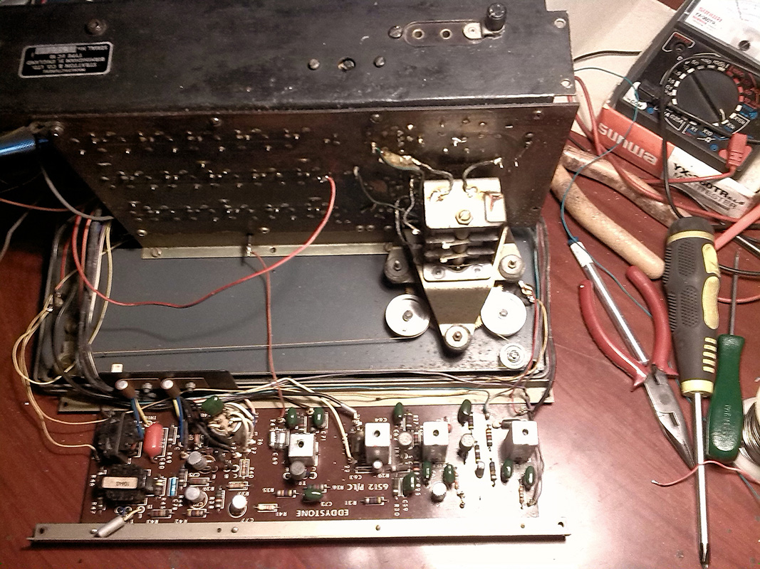
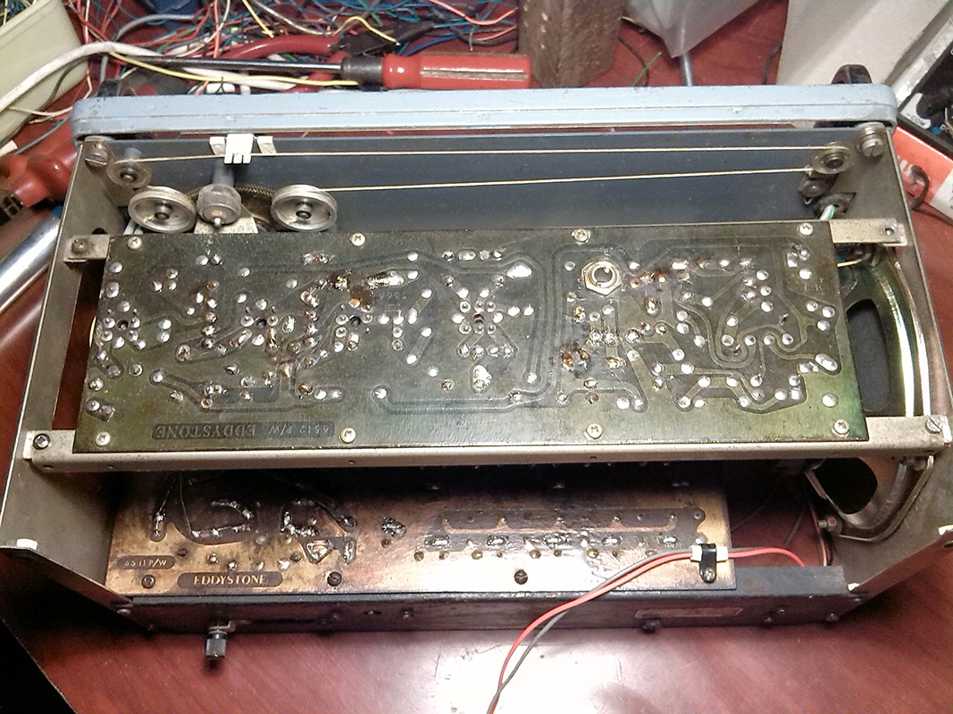
The main problems I found were corroded wires, components, and PCB traces. I worked through the restoration step by step, and the key steps are documented below.

Restored EC10 HF communication receiver

Restoration Steps

01
Obtained the EC10 MK1 schematic from the Eddystone User Group. The MK2 schematic is very similar to MK1 - the main differences are an additional fine-tuning control and a carrier level meter.
02
Removed approximately 75% of the capacitors. Most are located on the top (green) PCB. Capacitors on the bottom PCB are more difficult to access due to the mechanical layout - the channel selector switch needs to be disassembled to reach some of them.
EC10 repairing process on IF and AF amplifier board
EC10 repairing process - IF and AF amplifier board
03
Left all inductors and trimmer capacitors untouched - they appeared fine and did not require replacement.
04
Replaced two OC171 transistors (TR3 and TR5) due to the well-known tin whiskers effect - both showed short-circuits between Collector and Shield pins. I had spare OC171s in my collection so I replaced them rather than cutting the Shield pin. See this forum thread for more details on this issue.
OC71 transistors comparison
(a) Damaged OC71 transistor   (b) Working OC71   (c) AC125 as a direct replacement for OC71
05
Replaced OC71 transistor TR7 whose base lead had corroded and disconnected. Initially used a new OC71, then swapped to an AC125 - no measurable difference in performance between the two.
06
Completed full rewiring - replaced all wires with new stock, organised in the same harness layout as the original.
EC10 after rewiring and component replacement
EC10 after rewiring and component replacements. Both PCBs coated with protective plastic lacquer.
07
Both original dial lamps were burned out and difficult to source locally. Replaced with two high-brightness white LEDs connected via 1.2 kΩ resistors on the existing lamp connections.
Wiring diagram for LED dial light
Wiring diagram for LED-based dial light
08
Replaced the original 5-inch 3.2Ω speaker with a new 4Ω 12W 5-inch full-range speaker, as the original impedance is hard to source locally.

Integrated Power Supply

In this restoration I replaced the majority of passive components - a large number of capacitors, a few resistors - while keeping all inductors and trimmers in place. This means the receiver should need minimal realignment. I aligned the dial indicator using another shortwave radio as reference.

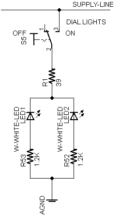
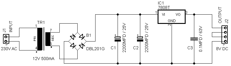
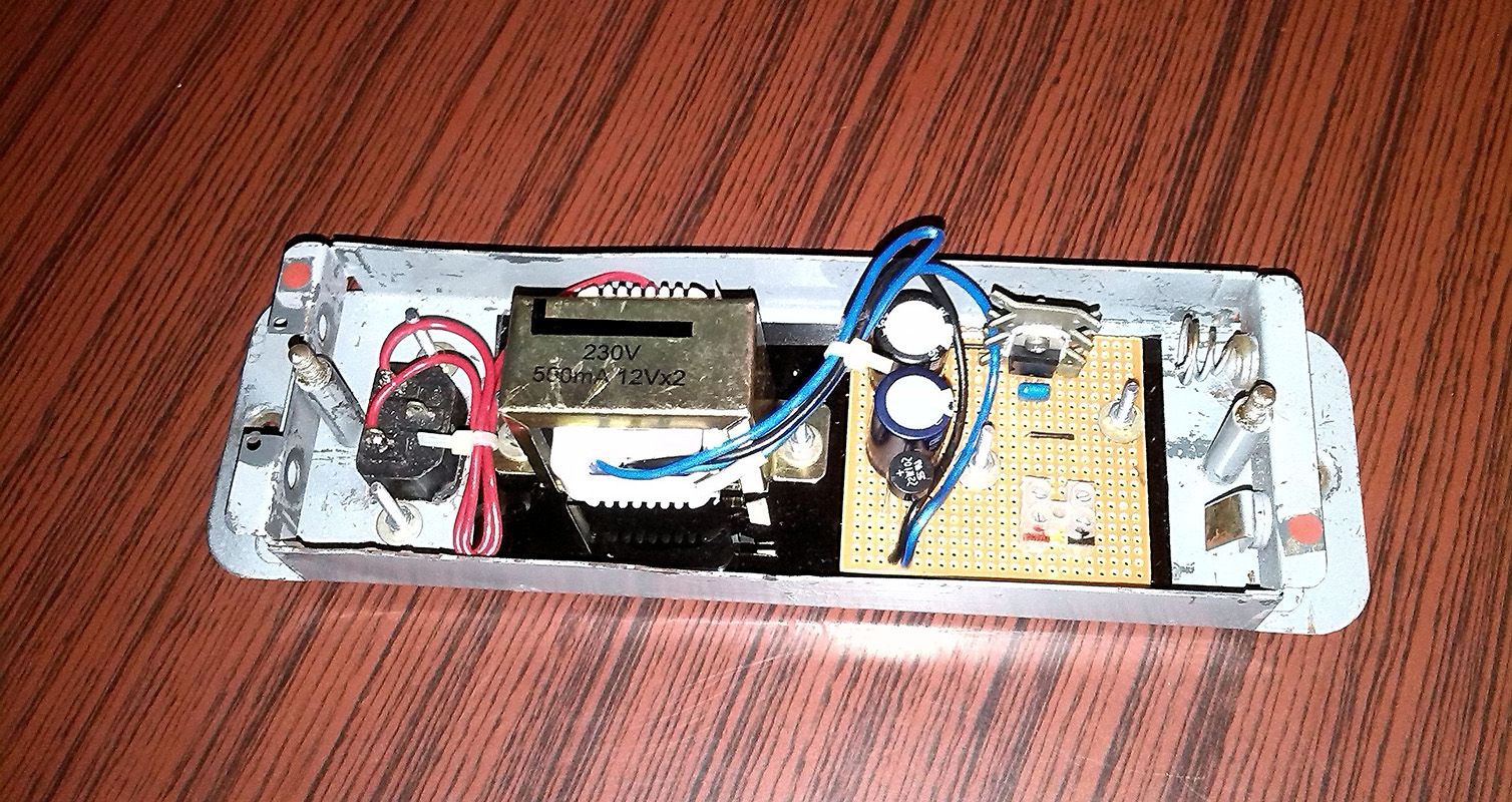
Running the EC10 on batteries is impractical, so I decided to integrate a small PSU directly into the receiver. During testing it drew very little current (approximately 0.08–0.02 A), so I built a compact 8V 500mA supply using a 7808 positive voltage regulator, fitted into the battery compartment.

8V PSU schematic
Schematic - 8V power supply unit
PSU installed in battery compartment
8V 500mA PSU fitted in the battery compartment

After completing all the above work, the EC10 came back to life and performs well with an external antenna. I regularly use it to monitor the 4S7RS net on the 40m band (7060 kHz).