I recently acquired a Trio (now Kenwood) JR-310 and TX-310 SSB receiver and transmitter pair. Both units arrived in very poor condition - chassis and PCBs were covered in dust, and several components were badly damaged. After examining both, I decided to restore them for their vintage value and the experience of operating a tube-based SSB transceiver pair.
I started with the JR-310 receiver, then moved to the TX-310 transmitter. Restoration steps are documented below.
05
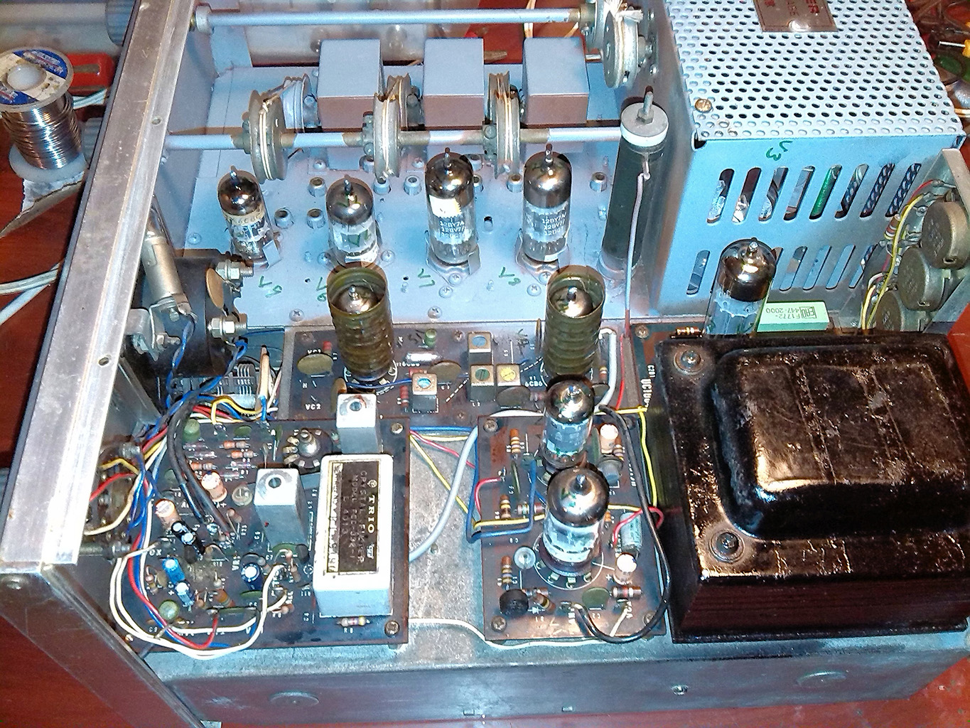
During initial testing there was no audio output. The fault was traced to the V2
6BA6 tube. Replacing it restored normal operation.
06
S-meter showed no deflection. Traced to incorrect wiring of VR4 (500Ω S-ADJ potentiometer). After rewiring, also cleaned VR4 with isopropyl alcohol to resolve intermittent readings.
-
After the above steps the receiver returned to full operation, supporting AM, SSB, and CW modes. Operating bands: 3.5, 7, 14, 21, 25, and 50 MHz. Sensitivity approximately 1 µV.
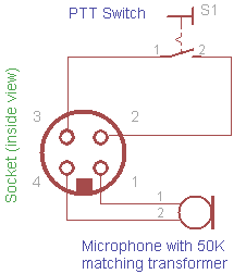
To test the transmitter, VFO drive must be supplied from the JR-310. The connectivity and microphone wiring diagrams are shown below.