Microwave Equipment of
VK3BJM.
Way up above our UHF allocation lay the microwave
bands. In Australia Amateurs have
access to the 23 cm Band (1.24-1.30 GHz), the 13 cm Band (2.4-2.45 GHz), the 9 cm
Band (3.3-3.6 GHz), the 6 cm Band (5.65-5.85 GHz), the 3 cm Band (10.0-10.5 GHz),
the 1.25 cm Band (24.0-24.25 GHz), the 6 mm Band (47.0-47.2 GHz), and there are
more above those!
Operating at these frequencies is a real challenge – but success brings real satisfaction! The majority of these bands require you to build your own transmitters, receivers and antennas. Only with the 23 cm Band is there any chance you’ll find commercially made, plug-and-go gear available – generally at three times the cost of doing it yourself.
Don’t feel daunted by this; there are plenty of good
kits available. All you need is good
eyesight (the components can be very small – they don’t call ’em microwaves
for nothing!), good soldering skills and steady hands.
The other challenge at these frequencies is in the
nature of propagation. Amateur Radio
continues to be a major data collection tool in determining how microwave
signals get from Point A to Point B.
Water – moisture in the air, and clouds – becomes a factor. It can both absorb the signals (thereby
killing a signal path) at some frequencies; yet at other frequencies the
signals will be reflected, resulting in a propagation mode called
“Cloud-scatter”! Some Amateurs in
France and Italy have established a path over the mountainous (non line of
sight) border by bouncing signal off glacial ice on Mont Blanc!
In short, there is plenty of pioneering work
available in the microwave bands.
For my part, I have microwave equipment in various
stages of completion for the bands between 23 cm and 3 cm; 23 cm and 13 cm are
operational, whilst the other three bands require a little work. I’ll start with the 23 cm gear…
1296 MHz (23cm)
Below are pictures of my first 1296 MHz transverter. It is used with a 144 MHz transceiver to give coverage between 1296 and 1300 MHz, which is where SSB and CW activity takes place.
It consists of a number of kit modules sourced from
“Mini-Kits” which
were then assembled and joined together to form the transverter. In its current form it is capable of
generating 28 watts on transmit, and hearing signals down to about -125dBm.
 This is a block diagram
showing the modules and the RF signal paths between them. While the two Mitsubishi M57762 power
amplifier modules are rated at 10 watts, they can be run to slightly higher
levels before saturation or distortion takes place. Mine are ok to 15 watts, but I tend to run them at about 14 watts
each.
This is a block diagram
showing the modules and the RF signal paths between them. While the two Mitsubishi M57762 power
amplifier modules are rated at 10 watts, they can be run to slightly higher
levels before saturation or distortion takes place. Mine are ok to 15 watts, but I tend to run them at about 14 watts
each.
I originally used a single
10-watt power amplifier module, and a small case for the modules. When I started exploring the long distance
AEP paths, I wanted to try 23cm as well as 144 and 432 MHz, and decided a
little more power would be a good idea.
This meant a far bigger heat sink, and a larger sturdier case to mount
it all in – I also had to find room for the associated splitter and combiner
modules.
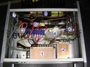
On the left is the view of the upper
compartment. Visible are: (1)
Interface, (2) Local Oscillator, (3) DC power rail, (4)
Pre-amplifier, (5) Coax relay and 12>24v converter, (6)
Combiner, (7) 144MHz connector and (8) Power amplifier and heat
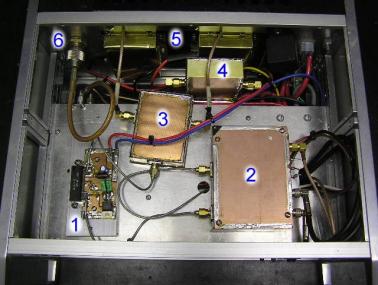
sink assembly. On the right is the view
of the lower compartment, showing (1) Transverter, (2) 1 watt
power amplifier, (3) Splitter, (4) Combiner, (5) Power
amplifier and heat sink assembly and (6) 1296 MHz antenna connector.
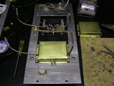

On the left is the rear panel with the two M57762 PA
modules mounted on the heat sink, with the brass RF shield in place over the
nearest module. Hardline is used to
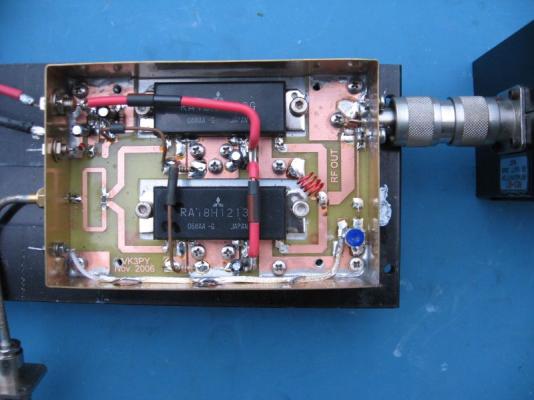
connect the outputs to the combiner. On
the right is a topside view of the actual transverter module, with (1)
144 MHz IF in and (2) out using the black coax and (3) the Local
Oscillator signal via the light brown Teflon coax on the left side of the
board; and semi-rigid coax carrying the 1296 MHz signal (4) in and (5)
out on the right side of the board.
Whilst this worked, I naturally wanted more power. About the time I damaged the combiner (long story…) Chas VK3PY contacted me. He was putting the finishing touches on an article for AR describing the building of a 60-watt SSPA, using a pair of the new Mitsubishi RA18H1213G power modules (the replacement for the obsolete M57762 module), and he wondered if I’d be interested in “proofing” the article the hard way; i.e., building one. Actually, it was the easy way, as Chas provided me with the PCB already etched... I agreed, and soon I had the new SSPA in place and generating a healthy 60 watts.
Next came the desire to have separate home station and field station capability; in other words, not have to disassemble the home station every time there was a Field Contest or Dxpedition. I’ve now built a second transverter, again based around the range of kits available from MiniKits. The transverter unit can provide up to 30 watts out, using a single RA18H1213G power module. This, in turn, will drive the external SSPA, based around two of Jim (W6PQL) Klitzing’s 150-watt amplifier kits. Each kit uses a pair of XRF-286 MOSFETs, and when combined should see me with up to 300 watts. The transverter unit has been set up for dual-feeder working; instead of a combined Transmit/Receive socket and an internal changeover relay, it has separate Transmit and Receive sockets and the (high power) changeover relay is located in the masthead enclosure.
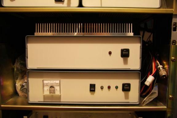
The new transverter (bottom) and 300-watt SSPA (top).
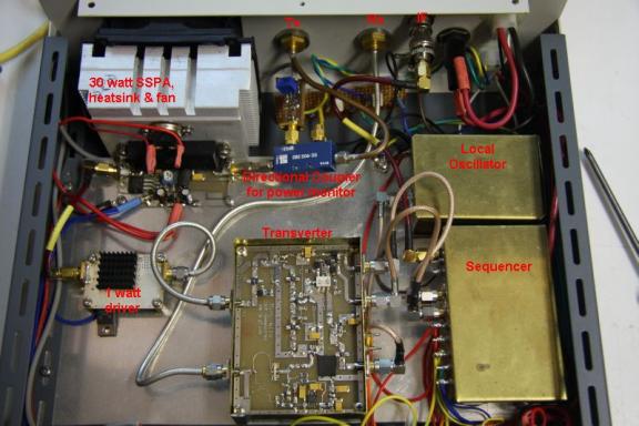

Left: Inside the new
transverter case. Right: the layout of
the 300-watt SSPA – a work still in progress.
To be continued…
Last update: 25/5/2011
|
|
||