|
|
|
The Tank Project |
|
K2 #177 |
|
K2 Bicycle Mobile |
|
MultiPIG |
|
Projects |
|
PIC µControllers |
|
Antennas |
|
Mobile Computing |
|
What's QRP? |
|
Online Log (old) |
|
About Me |
|
MX Riding |
|
My "Ham History" |
|
QRP Wattmeter |
|
SW40+ |
|
There have been |


|
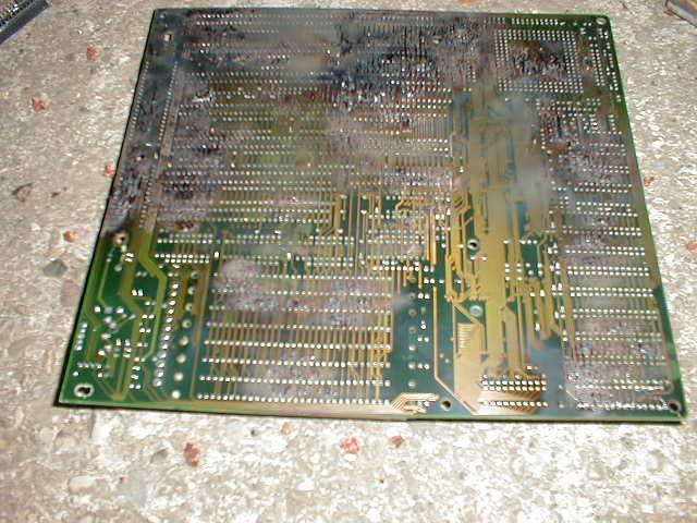
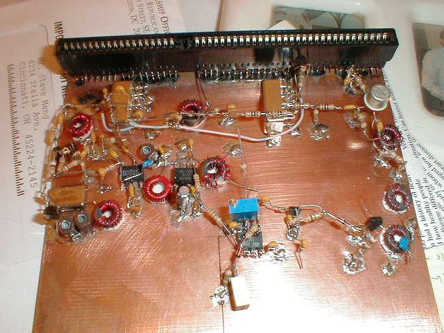
The transceiver section of the MP20 contains most of the actual "radio" of the rig. It has the mixers, IF amp, variable-bandwidth crystal filter, AGC circuit, and BFO. The audio amp is also part of this section. However, the transmitter and filters are on the Band Module board. The band module board plugs into the XCVR board with an ISA connector. The ISA socket is scrounged from an old PC motherboard.
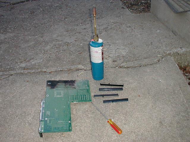
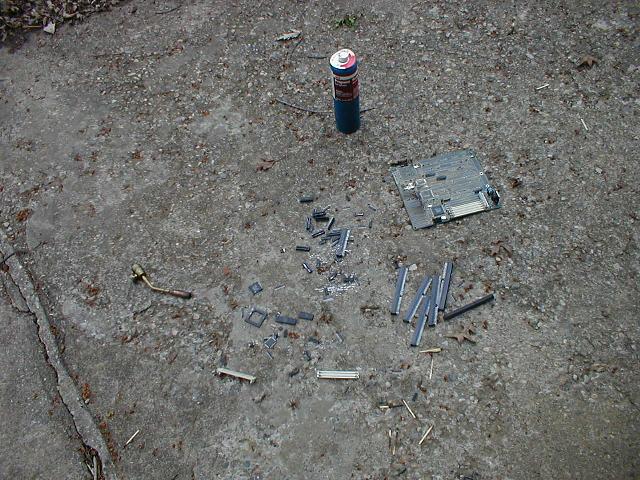
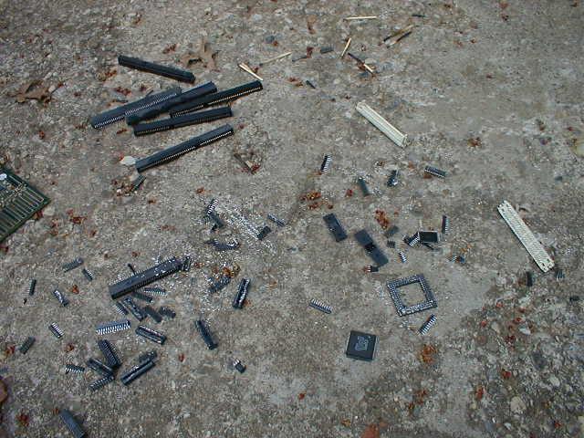
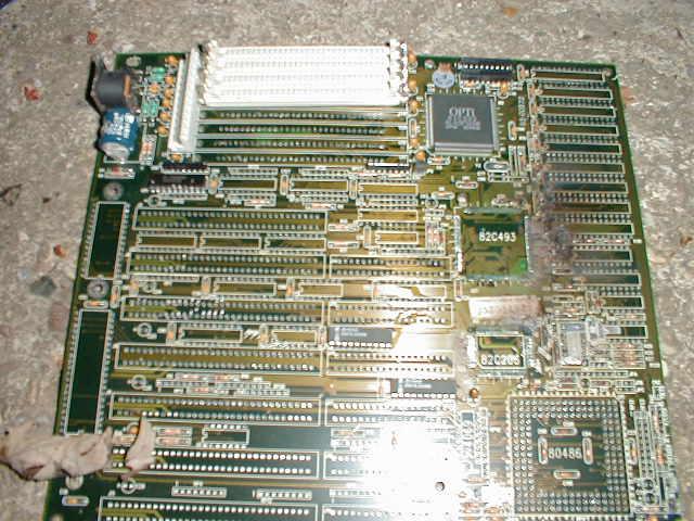
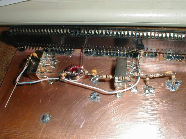
Lesson 14 Lesson 14 involved removing an ISA socket from a computer motherboard to use as the band module connector, and also mounting this connector, the mixers, and some associated components. I had a couple of old motherboards with a total of 10 ISA sockets. On the second board I was having fun, so I decided to see how many components I could get off with a propane torch by itself, and some banging to get out the parts when the solder was melted. There are a couple pictures of that. :-) I did get some useful 28 pin sockets I can use with the big PICs. I sent nine of the ISA connectors to Mac AF4PS for redistribution to the other MP builders who needed them. I mounted mine to the PC board, and built up the mixers and added the other parts. I just used point-to-point wiring instead of the terminal strip suggested in the lessons. I think it is lower-profile and a lot more compact.
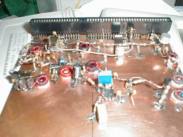
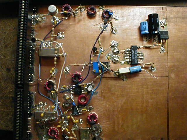
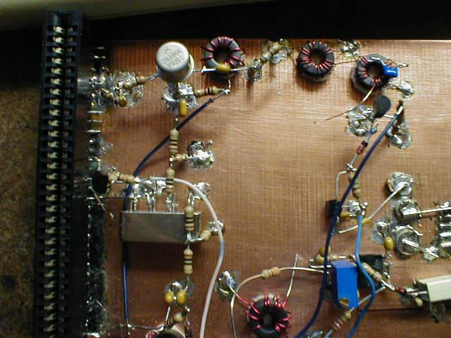
Lessons 15-20 This lesson involves the BFO and the NE602 mixer IC. I started to do this not really according to the lesson, since my space requirements were somewhat different (I have a corner of the board missing to fit the PLL tune cap (C25) when I stack the XCVR board on the PLL board). I just went by the schematic, and since I wasn't really looking at the lesson much, I kept on going. :-) I couldn't stop! This is just too much fun. :-) So from this point on, the lessons kind of blend together (I did most before they were even out, just following the schematic). However, I am waiting on the crytal filter; I want to arrange that right. Here are some pictures from a couple points along the build process.
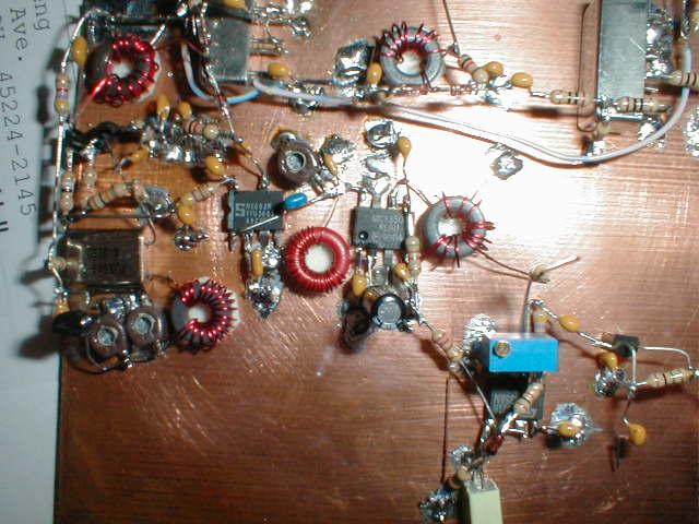
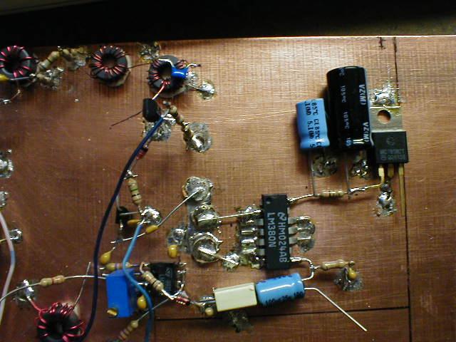
Lesson 21 Lesson 21 was kind of neat. It involved building the crystal filter on a small piece of PC board. The crystal filter for the MP20 is a 5-pole (in my case, others have a 7-pole), variable bandwidth design. It can be varied from a wide bandwidth for receiving SSB signals to a very narrow bandwidth for receiving CW signals that are down in the noise. Anyway, this was really quick and there are some pictures of it below on the finished board pictures. Finished Board Here are some pictures of the finished board; the crystal filter, AF gain pot, and coax from the PLL have been added here. |

[Mobile Computing] [What's QRP?] [Online Log (old)] [About Me] [MX Riding]
[My "Ham History"] [QRP Wattmeter] [SW40+]
This page last updated 12/22/01.
© 2001 N8MX.