|
|
|
The Tank Project |
|
K2 #177 |
|
K2 Bicycle Mobile |
|
MultiPIG |
|
Projects |
|
PIC µControllers |
|
Antennas |
|
Mobile Computing |
|
What's QRP? |
|
Online Log (old) |
|
About Me |
|
MX Riding |
|
My "Ham History" |
|
QRP Wattmeter |
|
SW40+ |
|
There have been |


Antennas
|
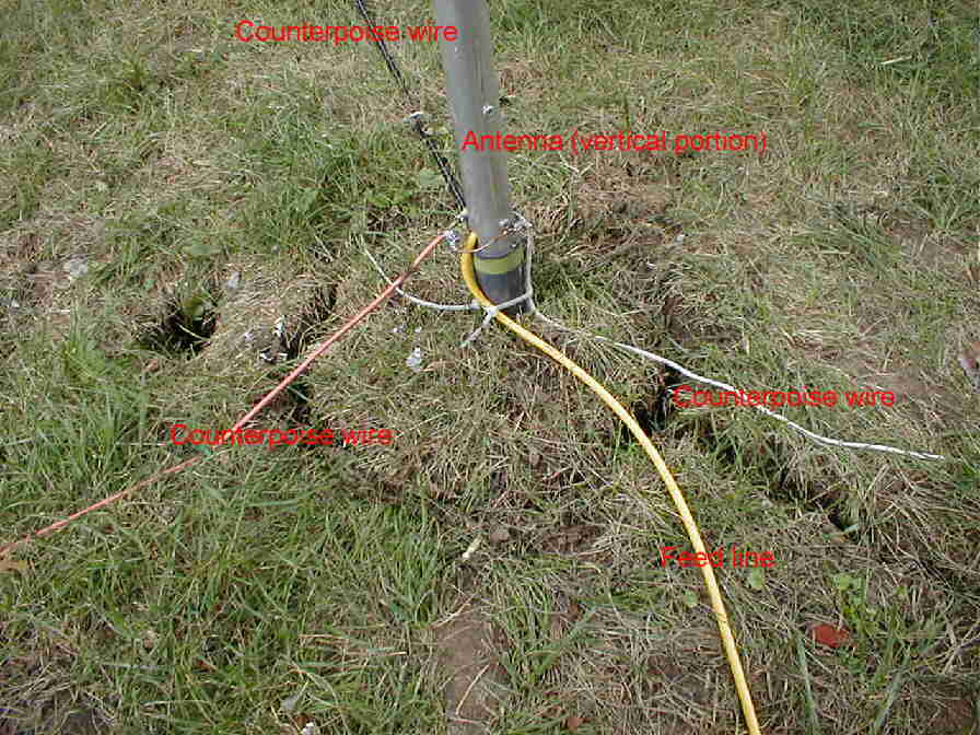
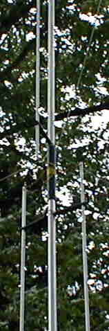
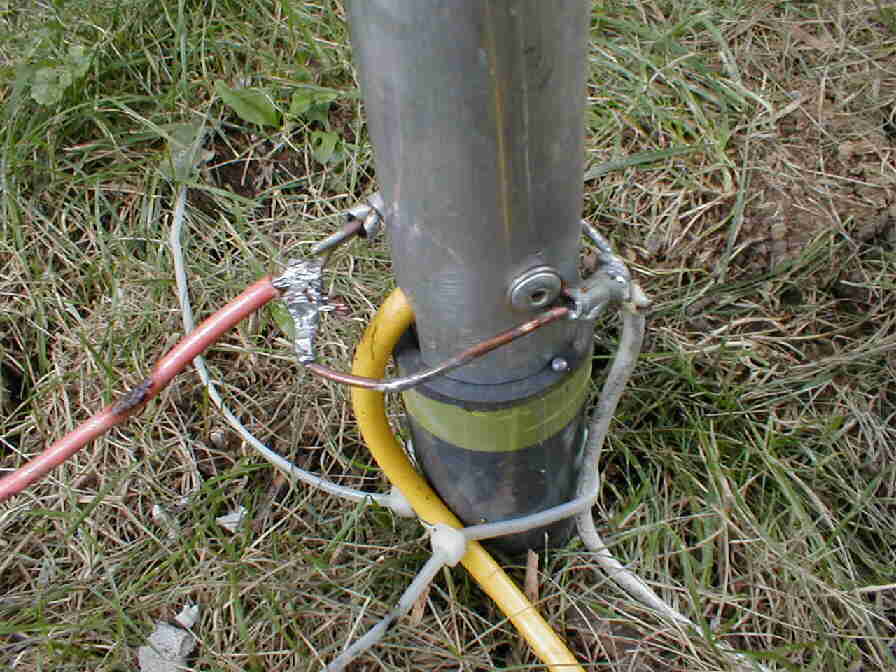
I bought a GAP Challenger antenna around the middle of this summer from R&L Electronics. When we got home, I took it out of the box, and started assembling it on the living room floor. There is one major change I made in the assembly. Instead of using screws to join the pieces, I used rivets. I had been reading all of the Force 12 literature, since I planned to buy a C3SS beam from them (I got the GAP because I decided that I could buy some other stuff this summer, and I wouldn't need to put up the tower and get a rotator to use it), and what I really liked about their construction technique was that they didn't use screws or hose clamps at all: all joints were riveted. This offers the advantage of not having fasteners that can loosen, but most importantly, rivets don't chew up the aluminum like a screw does. I screw is easier to get out, but really butchers the aluminum. Rivets are easily drilled out (I have already taken out a few). ed note: and left them in the driveway. So when I assembled the GAP, I used rivets. This required most of the holes to be drilled or reamed out a little. When I was done assembling the small sections of the antenna, I moved the pieces down to the garage, and finished the assembly there. The only problem I had was sliding the entire lower section into the plastic feedpoint insulator. I couldn't push it in to where the holes were showing (it was only an inch or two away), so I just drilled new holes. I finally got the antenna completely assembled and took it outside. Our basketball pole has a plastic sleeve set in concrete to make removal of the basketball pole easy. I took out the pole, and put the Challenger in the sleeve. Over the course of a couple weeks, I connected the three required 25 foot counterpoise wires and guy ropes just above the feedpoint. However, my mom and sisters wanted to be able to play basketball, so I was forced to move the antenna. One Saturday in the middle of August, I removed the antenna from the basketball pole hole. After consulting with my parents, I decided on a good location for the antenna with no metal very close, and almost hidden from sight from the house by two large trees. I first tried to make a hole by driving a pointed 4" PVC pipe into the ground. When I thought I had it pretty deep, I drilled a hole in each side and inseterd a pipe through the holes. I put a jack on each side and lifted out the pipe. I was very disappointed when I saw that the hole was only about 8" deep! I borrowed a post-hole digger from the neighbors, and dug a hole about 12" in diameter at the top and 3 feet deep, as called for in the GAP instruction sheet. I lowered the antenna in, tied the guys to nearby trees, and packed a foot of dirt into the bottom of the hole. The next Saturday, I bought three bags of concrete from the hardware store, and mixed up about 1/2 a bag at a time in a 5 gallon bucket. I hauled the half-full bucket over to the antenna and poured each load in the hole. After only the second bag, I had the concrete to within about 4" of the top. I stopped there. I next tried to install the radials. I took a spade, and cut a narrow slit in the ground and placed a counterpoise wire in. It took forever to do just a 25' wire, and the mosquitoes were awful. Also, the end of the wire was about 8' closer to the antenna than when I started, due to the vertical "waviness" of my burial method. I sent out an email to QRP-L that night asking how to bury the radials and the coax. I got some great, detailed responses, most saying: don't bury the coax, and I needed larger wire, and that I probably shouldn't bury that either! Saturday, September 2nd, I soldered a little wire ring to the base of the antenna. Onto here I soldered the counterpoise wires. Two of the wires are #12, one solid and one stranded, and the other is a 25' length of RG59 coax, with the center conductor shorted to the braid. This took some work, involving a propane-powered soldering "iron" (actually a torch heating a copper soldering tip!) and a Weller pencil-type (with a base) iron with a big tip. When I had this done and the radials stretched out in low-cut strips in the yard, it started to rain. I quickly put the tools away, and grabbed some tie-wraps to put a starin-relief on the solder joints. Unfortunately, I missed one of the wires (you can see in the pictures, it's the orange one), and so when I stapled it to the ground, it is not coming from ground level. When it stopped raining, I made up some staples out of about 6" of big copper wire bent into a U-shape. I installed these on top of the wires to hold them tightly to the ground, so they don't get hit by the lawn mower and so that the grass will grow around them. I found that the best way to do this was first put in a steel wire and move it around so that the copper wire already has a starting hole. This worked very well, otherwise the copper bent when I tried to push and hammer it into the ground. I finished this Labor Day afternoon (today), and the radials are hard to spot from the house, and even far enough away in the yard. I am pretty impressed with this technique that some suggested. Here are some pictures (click them for a larger picture):
 |

[Mobile Computing] [What's QRP?] [Online Log (old)] [About Me] [MX Riding]
[My "Ham History"] [QRP Wattmeter] [SW40+] [Home]
This page last updated 4/13/2002.
© 2002 N8MX.