|
|
|
The Tank Project |
|
K2 #177 |
|
K2 Bicycle Mobile |
|
MultiPIG |
|
Projects |
|
PIC µControllers |
|
Antennas |
|
Mobile Computing |
|
What's QRP? |
|
Online Log (old) |
|
About Me |
|
MX Riding |
|
My "Ham History" |
|
QRP Wattmeter |
|
SW40+ |
|
There have been |


|
A Phase-Locked Loop (PLL) is a type of frequency synthesizer that uses a reference oscillator and some programmable dividers to compare the reference frequency and the output frequency. The error voltage from a phase-detector is amplified and sent to a voltage-controlled oscillator (VCO), where the frequency is set by the PLL IC. The output is fed back into the PLL and a feedback loop makes sure that it stays on frequency. The MP20 PLL is based on the K2 PLL. However, a parallel-input PLL chip (MC145151) is used in order to allow the user to set the frequency manually. Another aspect of the K2 and MP20 PLLs is the large variable capacitor across the variable-capacitance diodes (MV209 varactors). The large capacitor is used to achieve a much wider tuning range than is possible with only the voltage-controlled ones. The user sets this capacitor so that the PLL tuning voltage remains close to the optimum voltage of the varactors. This voltage is displayed on an LED display.
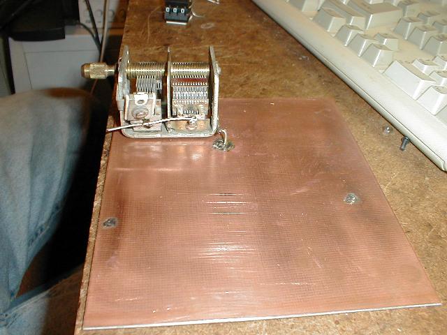
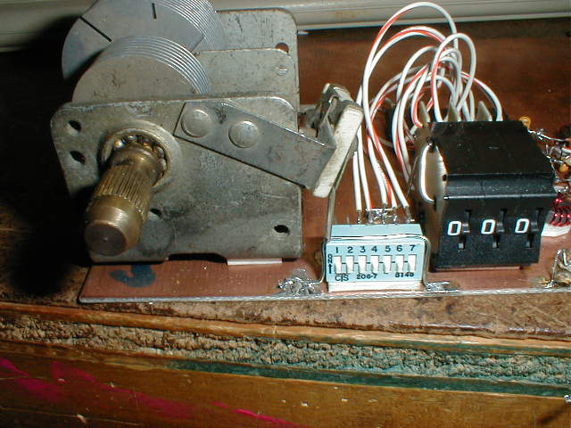
Lesson 7 Lesson 7 involved mounting of the C25 1000pF Capacitor, and assembling the octal switches. I used a dual-section cap here, and when the sections are connected in parallel, I get about 650pF. Diz said it should be enough for 20m, if I want to do 80m or 160m I will put another fixed cap in that I can switch in and out. The octal switch assembly was straight-forward, but instead of wrapping the wire around the front, I just used some heavy wire and bent it into a "U" shape that went through two holes in the switch bodies.
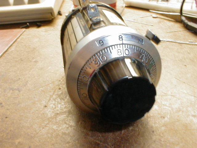
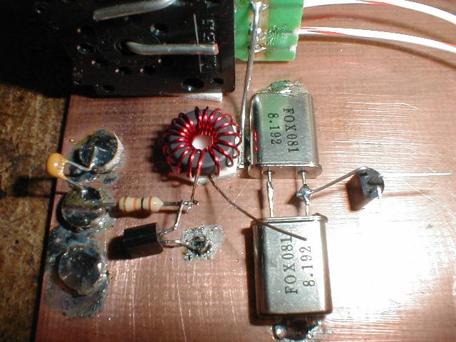
Lesson 8 Lesson 8 detailed construction of the PLL reference oscillator. This runs at around 8.192MHz, and it can be varied about 10KHz (mine only seems to be about 5KHz right now) by pulling two crystals with a varactor diode. This is controlled by the main tuning 10-turn potentiometer. This was a relatively easy circuit to assemble because it is pretty simple. Mine worked without making any major changes. I hooked it up to make sure it worked, so that if I had problems farther along in the construction, I would be able to rule out a problem in the reference oscillator.
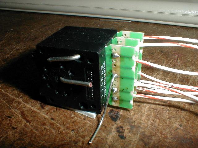
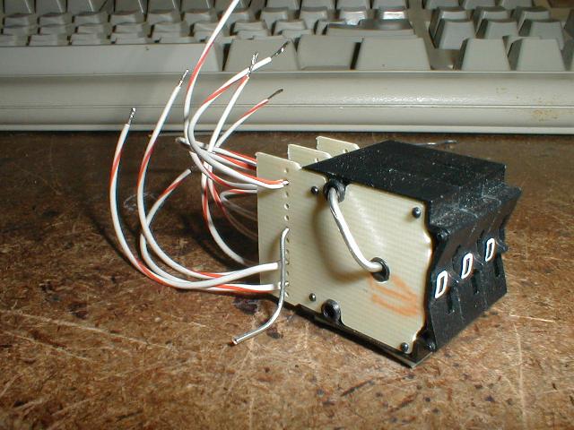
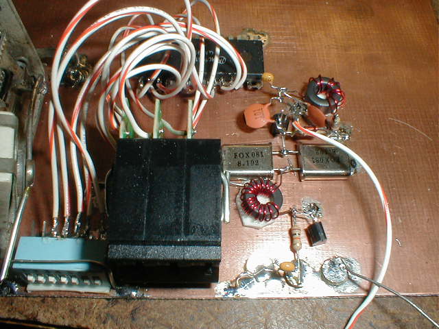
Lesson 9 Lesson 9 involved construction of the error amplifier and loop filter for the PLL tuning voltage. This was really packed in tight although there were not many parts. Here is a picture I took when I was done.
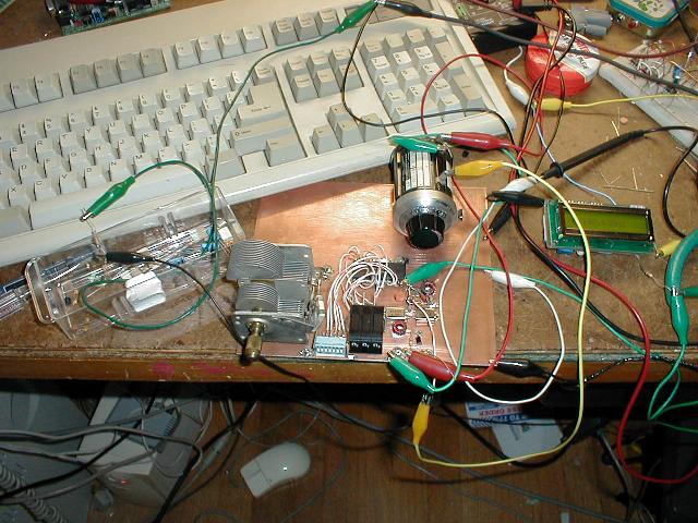
Lesson 10 Lesson 10 was quite a bit more challenging than Lesson 9. It involved construction of the VCO, buffer, and AGC circuit. I also added some final touches to the Frequency Counter, such as an RCA plug connector and jumper for the offset switching. Constuction of this section took awhile. I tried to be careful, because my parts layout deviated from the pictures in the lesson, so it took a little while to figure out where to position the parts so that they would end up close to where they needed to be when I finished a section. When I was done I checked my work over completely and also had my dad check it. I hooked up power, tuning pot, and the FC and turned it on. I got a frequency out, but it was not being controlled by the PLL. It changed directly as I turned C25, the coarse tuning cap. I hooked up a current meter, and it was drawing 660mA in the PLL section alone. Some further testing and inspection turned up a bad ground connection on pin 2 of the PLL chip. With this fixed, it worked! I was pretty excited to have the PLL going, and I played with it the next few days. :-) The whole reverse-logic idea is pretty strange! Yesterday I got the voltmeter and band module parts from Diz and built the voltmeter last night. I got it hooked up and working. I found that my PLL only covered up to 23.5MHz, so I put a switch in one of the sections of my variable cap to switch out the capacitance from the larger section. A wire on T4 came off, but once I found it and soldered it back on, my PLL range went to 30MHz! So, that's pretty good and I'm happy with it.
|


[Mobile Computing] [What's QRP?] [Online Log (old)] [About Me] [MX Riding]
[My "Ham History"] [QRP Wattmeter] [SW40+]
This page last updated 12/22/01.
© 2001 N8MX.