IN3OTD's web site
...under perpetual construction.

Impedance fitting
When measuring components with a network analyzer, often is useful to fit a simple circuit model to the measured impedance.
The method described in [1] and [2] can be used to easily compute the equivalent circuit model parameters.
Below are some common equivalent circuits used, which are the same usually available on the Agilent Impedance Analyzers, and their recommended usage according to the Agilent User's Manual. The circuits impedance formula is also shown, both in its usual form and also in the form needed to apply the method described in the referenced articles.
Fitting procedure overview
Given a generic impedance function written in polynomial form
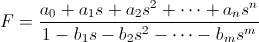 the following error function can be defined
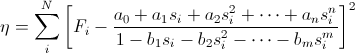 where
where  are the measured impedance function values at the frequencies
  .
.
By differentiating the error function  with respect to all the unknown coefficients
  and
and  and then setting all these derivatives to zero, a system of equations is obtained which allows to determine the unknown coefficients.
The matrix system has the canonical form
 where
where  is a
is a  matrix and
  and
and  are vectors of length
  , where
  .
.
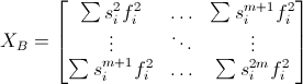
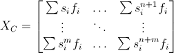
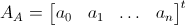
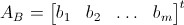
The matrix system can be written using sub-matrices as
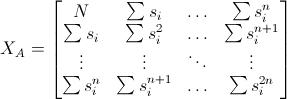
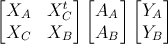 where the sub-matrices and sub-vectors are defined as


The matrix equation can then be solved by
 In practice two problems arise: one is that is a complex matrix, is also a complex vector while we expect to be a real vector. The other problem is that the condition number of is often very large, which can cause large errors when computing the coefficients.
Circuit A

Typical usage : inductor with high core losses
Impedance :
 Impedance function to be used for fitting :
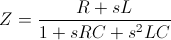
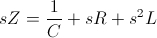
Circuit B

Typical usage : inductor or resistor
Impedance (already in a format suitable for fitting) :
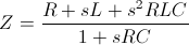
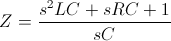
Circuit C

Typical usage : high-value resistor
Impedance (already in a format suitable for fitting) :
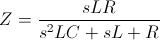
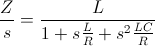
Circuit D

Typical usage : capacitor
Impedance :
 Impedance function to be used for fitting :
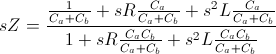
Circuit E

Typical usage : resonator
Impedance :
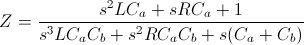 Impedance function to be used for fitting :
References: