This is a decade of synthesised radios, some still using the Wadley Loop principle, others, notably the 'premium' receivers, digitally synthesised, and locked to a common reference, often an OCXO for supreme stability.
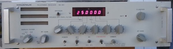
Hagenuk RX401 Marine Receiver (1980)
This receiver, manufactured by Standard Radio and Telefon AB, a division of ITT Sweden, was intended for use in the radio room of large ships, or at the corresponding shore stations. It is set up for duplex operation with a set of Duplex rejection filters for the marine bands. The lower marine bands (1.6 - 4.2 MHz) have a front-panel tuned 'Duplex Filter'. The rejection of a locally operated transmitter is at least 35 dB.
The receiver has excellent specifications for the time. With frequency coverage from below 100 kHz to 30 MHz, there are eight switched band-pass filters and a low-pass filter for LF. There is a cascode JFET preamp, which makes the receiver quite sensitive. The receiver is double-conversion, with a double-balanced diode first mixer, first IF of 63.078 MHz, a dual-gate FET second mixer, and 5 MHz second IF. It operates AM and SSB (USB only), with the 10 kHz AM filter acting as 'roofing' filter for the subsequent SSB filter. This receiver is also equipped with a third (optional) narrow filter for Telex (RTTY) operation.
The synthesizer arrangement uses TTL logic, and is quite complex, involving three loops to provide 100 Hz steps across the tuning range. A clarifier is provided by varying the 1 kHz reference to the major (high frequency) loop, via an interpolating loop. This is derived from a 10 MHz variable crystal oscillator. The minor loop provides the smaller steps. The second conversion local oscillator is fixed, generated from the 5MHz TCXO which acts as master reference.
The Hagenuk RX401 front panelThe red LED display is directly connected to the frequency control switches. The bandpass filter switching is also controlled by these switches. There is no means of tuning in this model other than the six BCD decade knobs, although it is apparent from the documentation and inspection of the mother board, that a version with a rotary encoder is also offered. There is also no front-panel headphone socket, just the loudspeaker, which is disabled when the Duplex option is engaged. All external connections are made via a DB15 connector at the rear.
Construction of the receiver is in a row of 11 Eurocard boards in a card cage at the back, with a full-width backplane board and a smaller mother board below. Access to the cards is from the rear, once the power supply and back panel have been removed.
In the above picture, the MF Duplex Rejector board is at the left, and the Telex IF filter board next to it. You can see that many of the ICs on the mother board are unpopulated - this will be the circuitry for the rotary encoder tuned model.
The power supply is a large box attached to the rear of the receiver. As well as conventional 115/230 V operation (auto-switched) there is also 24 V battery capability, with automatic switch-over. Power consumption is about 17 W. The power supply can be remote switched from the front panel.
The power supply alone weighs 4.6 kg, while the whole receiver weighs 7.2 kg. Dimensions are 482 x 410 x 135 mm, and the unit is rack mountable.
The Hagenuk RX401 oblique viewMy example of this interesting receiver has a complex fault in the minor synthesiser loop, but I have it running happily by disabling the 1st Local Oscillator VCOs, and injecting a 63 to 93 MHz signal from an external generator into the VCO wideband amplifier. It is also therefore possible to receive lower sideband by moving the external generator to the range 63 to 33 MHz, although tuning will be in reverse. A dedicated modern synthesizer and micro-controller would be a good permanent solution to the problem.

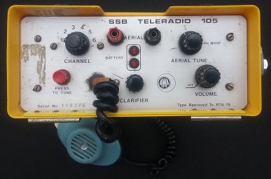
AWA Teleradio TR105 (1980s)
AM sets for HF service were phased out in the 1980s (details not clear) with the publication of a specification for SSB radios. The first of the new SSB radios for search and rescue, emergency and mountain radio applications was the AWA Teleradio TR105. Earlier models looked rather like the TR3 (above), with a separate battery back.
The unit I have is a later version, with a different front panel, proudly carrying the RTA19 type approval label, and a clip-on battery pack. The transceiver is reaonably showerproof. Like the TR3, it uses a permanently connected dynamic speaker-microphone. The transceiver came in a small tramper's pack, also containing spare battery pack and the antenna leads.
The transceiver is a single-conversion design with an IF of 1.4 MHz, using an LSB filter and crystals on the high side of the working channel. (I'm looking for a schematic of the radio). The transmitter ran 5W PEP output, and the performance was well in advance of the earlier AM sets.
The radio ran off nine D cells. It was primarily used on SAR and Police 2 MHz and 5 MHz channels
The AWA Teleradio TR105There are four operating controls: a VOLUME control (with power switch), a transmitter AERIAL TUNE control, a CHANNEL switch, a CLARIFIER control. There's also a 'Press to Tune' button. Adjustment is made by maximizing the brightness of an LED. A second LED indicates battery level.
On one side of the case is a whip antenna mount, for use with a short antenna while tramping. The mount connects to a fitting on the side of the radio via a push-on clip. There are terminals on the front panel for use with a wire dipole. The plastic case has internal metal shields top and bottom, which connect to the chassis when the radio is pushed into the case.
Sony ICF-2001 FM/AM PLL Synthesized Receiver (1980)
The title is that given by Sony in their user manual. As far as I am able to discover, this was the first ever portable dual conversion consumer radio to offer direct entry and PLL synthesis. Other direct-entry receivers at the time were desk-top models, not battery operated.There are a number of interesting features to the ICF-2001. It tunes in just two ranges, 150 kHz to 29.999 MHz in 1 kHz steps, and 76 to 108 MHz in 100 kHz steps. There's no 'tuning knob', although the receiver can be stepped at two speeds. Unfortunately the receiver mutes and makes noises as it steps.
This is a solid and sizable portable radio (310 x 171 x 56 mm), which runs (thirstily) off three D cells or an external 4.5V supply. It draws 190 mA on FM and 225 mA on AM, so the batteries last just 10 hours. There are six user frequency memories. Two AA cells keep the micro and memories alive.
The panel is well laid out, and the receiver is very easy to use, but best if laid flat or tilted using the rear hinged stand. There is a huge (1200 mm) telescopic whip which works on all bands, a ferrite rod which operates up to about 2 MHz, and 75 Ohm external input terminals which can be used over the whole reception range. If you use the receiver on a desk, flat or tilted, the antenna base needs to be pulled out slightly and rotated forward to allow the antenna to point vertically. The receiver has a plastic shoulder strap, but you'd not want to operate it hanging from your shoulder with the antenna extended!
The design is single conversion on VHF, with a 10.7 MHz IF with two ceramic filters. On MF/HF the design is dual conversion, with a 66 MHz first IF and PLL synthesised first local oscillator. The first mixer uses balanced FETs. The second conversion is to 10.7 MHz, using a VCXO which is fixed except in SSB where it acts as Clarifier. There are double-tuned coils and further ceramic filters in the MF/HF IF. The BFO is fixed at 10.7 MHz and a product detector is used for SSB/CW. This arrangement works because the second IF is relatively broad.
There is some anecdotal evidence that John Lennon owned one of these receivers, and there is a photo I've seen showing him in a studio with an ICF-2001.
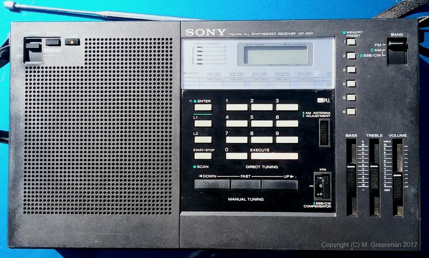
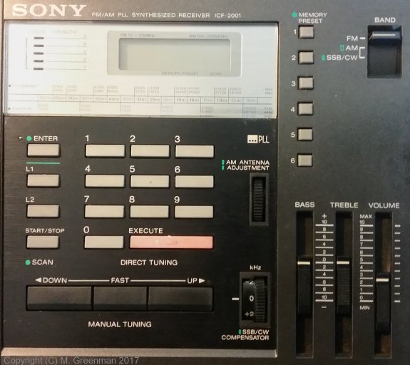
The Sony ICF-2001 Receiver (left) Detail of the receiver controls (right)
Sony ICF-6800W Short Wave Receiver (1981)
This radio is a complete contrast with the ICF-2001 listed just above, and yet it is of a similar age. The ICF-6800W came in two versions, 'white' (S/No below 30,000) and 'orange', the later and more desirable model. Unlike the keypad entry digitally synthesised ICF-2001, the ICF-6800W uses a multiple VCO arrangement and an interpolating VFO operating in a complex loop with the two VCOs. One of the VCOs operates in 1 MHz steps. The first IF is 19.055 MHz, and the second 10.7 MHz.The ICF-6800W covers 530 to 1600 kHz, 1.6 to 30 MHz, and 88 to 108 MHz FM. On short wave it has two AM IF bandwidths, plus upper and lower sideband options in SSB/CW modes. There is a short wave preselector with separate dial and control. The main tuning dial has a large drum display calibrated 0 - 1 MHz for short wave, and directly in kHz for the AM band. There is a red 5-digit LED frequency counter with 1 kHz resolution, which operates in AM and SW modes. The FM mode has a separate tuning dial, and no frequency counter function.
The appearance of this radio is most unusual. It is about the size of a bread bin (453 x 184 x 227 mm) and weighs 5.9 kg. The main tuning dial is cylindrical, edge on, and quite prominent, with a decent sized (dial cord operated) tuning knob to the right. The SW band selector (MHz control) consists of two concentric controls, one labelled 0 - 9, the other 0 - 10 - 20 MHz. These are interlocked to prevent you from selecting 00 MHz. There is an RF gain control which works on MW and SW. Many of the controls have small blue legends next to them, which indicate which modes (MW, SW, FM) they are active in. A simple and convenient idea. You can see them clearly in the photos below.
The unit is mains powered (rear selector 110, 120, 220, 240 V), from 9V using an external adaptor, or from six internal D cells, which conveniently fit under the hinged fold-down world map and band plan on the top cover. There is also space under the top cover for the power cord, which is a standard Japanese two-pin type. Unfortunately the Aust/NZ power plug is too big to fit in this space.
On the top lip of the back panel is a UHF connector used for all bands, and four push terminals for wire antennae for MW and SW. The tilting telescopic whip antenna is 1200 mm long, and has an accompanying switch to select it or the external antenna. There originally would have been brackets on the sides for a carrying strap, but these are long lost. A headphone socket is provided front left, but like the speaker, there's no stereo in FM mode.


The Sony ICF-6800W Receiver front view (left) Oblique view with hinged map displayed (right)

Rear view showing connectors and battery compartment (below)
Unfortunately my ICF-6800W is the less-desirable early serial number group (white labels), and even worse, there's a synthesiser fault, so it only goes on AM and FM. Also, neither the dial or meter lamps work, although there's a neat little lamp under the main dial provided so you can read your log book in the dark. I have the Service Manual and other documentation, and I'm led to believe that servicing this receiver is next to impossible!
Rohde & Schwarz ESM-500A VHF Receiver (1981)
This beautiful rack-mount surveillance receiver covers 20 - 1000 MHz (the A version), and is accompanied by the EZP Panoramic Adaptor. There is also a small panoramic display built into the receiver. The ESM-500A and EZP can be remote controlled via IEE-488 or RS232, and set to a resolution of 10 Hz. There is an oven-controlled reference providing 1 x 10⁻⁸ accuracy. There are two synthesisers, providing for double conversion. The first IF is 310 MHz or 810 MHz, and the second IF is 10.7 MHz. The receiver weighs 18 kg, and is rack mounted.Unfortunately my Rohde & Schwarz ESM-500A VHF Receiver is not operational, although the EZP Panoramic Adaptor works. I have the manuals.
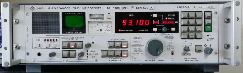
The Rohde & Schwarz ESM-500A Receiver
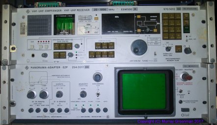
The Rohde & Schwarz ESM-500A Receiver and EZP Panoramic Adaptor
Wandel & Goltermann SPM-30 (1982)
This handy device is a complete Selective Level Meter and Tracking Generator in a single compact box. It operates from 200 Hz to 1.65 MHz, and is fully synthesised. Internally, it is well laid out, with the RF sections in die-cast boxes, and the digital and low frequency circuitry on plug-in boards. It should be straight-forward to service.The First IF is 4 MHz, so the first local oscillator VCO tunes from 4 MHz to 5.65 MHz in 1 Hz steps. The second IF is 10 kHz, and the second local oscillator is fixed and derived by direct division from the 8 MHz main reference oscillator, as is the BFO.
Remarkably, the unit has no micro-controller, yet offers digital tuning, digital display, and will also recall the last used frequency upon power-up! Frequency control is achieved using a rotary encoder with Up and Down outputs, operating a seven-decade up/down counter to store the operating frequency. This controls the main VCO via a D-A converter and digital phase detector.
There is a 600 Ohm audio output (but no speaker), and the receiver offers USB and LSB operation and bandwidths 3100, 1740 and 24 Hz. The large meter indicates level in dB and dBm, and the sensitivity is around -120 dBm.
Frequency calibration is correct when the SSB audio pitch is 2000 Hz, either USB or LSB. When an AM signal is zero-beat, the audio sounds very good on the wider bandwidth, although the frequency display reads exactly 2 kHz in error, low on LSB, high on USB.
The unit is built into a sturdy die-cast clam-shell case with Aluminium subframe and front and rear panels, which are silk screened. Designed for operation from large internal NiCd cells (not now fitted), it will also operate from 115/230 V AC (25 VA). The unit is 317 mm wide, 175 mm high, 342 mm deep, and weighs 12 kG (11.1 without battery).
I have the manual, diagrams and schematics.

The Wandel & Goltermann SPM-30 Selective Level Meter & Tracking Generator
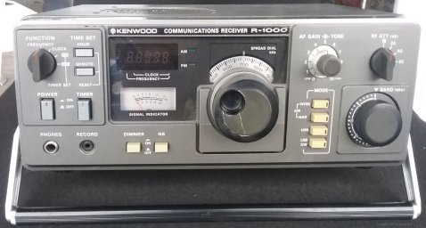
Kenwood R-1000 (1979 - 1985)
Quite a contrast to the Wadley Loop receivers of an earlier generation, the R-1000 heralded an era of multi-loop PLL synthesis receivers, using a VFO to interpolate between 1 MHz steps. A small processor is used to read the band switch, select the PLL settings, the bandpass filters and operate the frequency counter and display. This is a similar arrangement to the TS-120S and TS-130S transceivers of the same era.With just two frequency related controls, Band and Tuning, the R-1000 is exceptionally easy to use. Not quite as stable as we've come to expect these days, nevertheless the receiver is adequately stable for SSB after warmup, although tuning requires care. The receiver operates from 200 kHz to 30 MHz.
The receiver employs PLL synthesis in two steps, using a common reference. It uses double conversion. The first IF is 48 MHz and the second 455 kHz, where there are wide (12 kHz) and narrow (6 kHz) AM filters, and a 2.7 kHz SSB filter. The BFO injection is derived from independent crystal oscillators, and results in the digital display reading 1.5 kHz in error (opposite directions) on USB and LSB. The display indicates in 1 kHz steps.
As is common in 'short wave' receivers of the time, the R-1000 includes timer and tape recorder functions. There is a useful four-step RF attenuator. The loudspeaker is in the top cover.
I bought an R-1000 new in about 1981, and later regretted selling it. The receiver I have now is of similar vintage, and shows its age with iffy switches and a noisy volume control, but otherwise goes fine and looks good.
The Kenwood R-1000 Receiver
Kenwood R-600 (1982 - 1985)
The Kenwood R-600 is technically similar to the earlier R-1000, and is the same physical size. It lacks the timer function, has fewer controls and consequently is simpler to use. They have replaced the earlier (and unreliable) push-button mode switches with a solid rotary switch. With fewer controls, the speaker is now on the front panel, and gives good sound.The receiver operates 150 kHz to 30 MHz in 1 MHz ranges. There are two selectivity settings: 6 kHz (AM wide) and 2.7 kHz for AM Narrow, USB and LSB/CW. It would be helpful if there was a wider option on AM.
The frequency synthesis system uses triple conversion. The first IF with roofing filter is 40.455 MHz. The synthesised first local oscillator is interpolated between 1 MHz steps using a VFO. The second IF is 10.455 MHz, and the third is 455 kHz, where selectivity is provided by ceramic filters. The second and third local oscillators are fixed at 30.0 and 10.0 MHz, and derived from a common 10 MHz reference. The first two mixers are both balanced FET types, while the third is a dual-gate FET. The product detector is a diode bridge and uses an LC oscillator switched between 453.4 and 456.6 kHz. On SSB the frequency display reads 1.6 kHz in error, as the BFO frequency is not compensated for. A small processor is used to read the band switch, select the PLL settings, the bandpass filters and operate the frequency counter and green 7-segment LED display, which indicates with 1 kHz resolution.
With just two frequency related controls, Band and Tuning, the R-600 is simple to use. In fact, it's a real pleasure to use, is adequately stable, and tuning SSB signals isn't difficult. This model has an optional 12V DC power input, but it's not fitted on my receiver.
The receiver is cosmetically in reasonable condition, with minor damage and a scratched top cover. Electrically it is in excellent shape. When it arrived there was one annoying fault - the display occasionally went out and the receiver stopped, probably due to a bad connector. I wiggled and removed all the connectors, and I believe that's now fixed.
The Kenwood R-600 Receiver

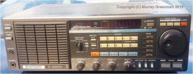
Kenwood R-2000 (1982 - 1992)
I have two of these good looking receivers, one made in 1984 in really good working order, good cosmetically, and complete with the VHF converter.I have a second working receiver (made 1983) in slightly rough condition, with arrived with several faults, most notably a problem with the rotary encoder. That's now fixed, but it still has other issues. These receivers were made over much the same period as both the R-600 and R-1000 receivers.The Kenwood R-2000 is a triple conversion triple-loop PLL synthesis radio. The IF frequencies are 45.9 MHz, 9.9 MHz and 455 kHz. The receiver range is 150 kHz to 30 MHz, plus 108 - 174 MHz if the VHF converter option is fitted. Operating modes are AM, FM, SSB and CW. There are wide and narrow filters for AM, and an optional narrow filter for CW (which is fitted in mine). The frequency display indicates in 100 Hz steps, which coincides with the minimum synthesiser resolution. There are three tuning speeds provided, plus a tuning lock. There are also up/down buttons which step the frequency in 1 MHz steps. The display is the vacuum fluorescent type. There are eight programmable memories, and the current memory number is also displayed. The receiver has scanning mode, with memories used to set the scan edges.
As is common in 'short wave' receivers of the time, the R-2000 includes timer and tape recorder functions. There is a useful four-step RF attenuator. The good-sized loudspeaker is well placed on the front panel.
There is a noise blanker option, all-mode squelch, and an AGC fast slow switch. There is an internal AC supply. Power consumption is 14 W, and the receiver draws 600 mA when running from 13.8 V DC (a fitted option). The receiver dimensions are 375 x 115 x 210 mm, and it weighs 5.5 kg.
The Kenwood R-2000 Receiver
Watkins-Johnson WJ-8718A/MFP HF Receiver (1982)
Not the prettiest monitoring receiver, this is however a top-of-the-line professional unit with excellent performance. It's not small - rack mounted, and 500 mm deep! It weighs nearly 16 kg. The front panel is clear enough, with large cream buttons, some with LED indicators, but not laid out very sensibly. Those large buttons take up most of the panel space, but at least they are decent reliable switches. The meter top left is calibrated and can indicate audio line level or signal strength.The receiver operates AM//FM/USB/LSB/ISB and two CW modes, with variable and fixed BFO. All oscillators are synthesised from a common 1 MHz high stability OCXO, or can be externally locked. It operates from 5 kHz to 30 MHz, and has a step resolution of 10 Hz. The yellow LED frequency display is excellent, and there are similar auxiliary displays for memories and BFO offset.
The receiver has high dynamic range performance with 10 sub-octave preselector filters, and several other options fitted, including 455 kHz IF output, IEE488 remote control, carrier operated relay, and of course it is the microprocessor- controlled version.
The receiver uses a first IF of about 42 MHz, second IF 10.7 MHz and third 455 kHz. Five IF filters are offered, from 16 kHz down to 300 Hz bandwidth. The BFO will tune �8 kHz, so with 16 kHz bandwidth, can demodulate wide-band data transmissions. There is no internal speaker, so I have rigged up a pair of old computer powered speakers to the Line terminals on the back, cunningly wired so that in ISB mode the LSB signal comes out the left speaker, and the USB signal out the right! You can tune stations with stereo effect!
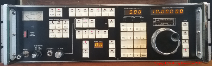
The Watkins-Johnson WJ-8718A/MFP receiver
Regco (RACAL) RG-5554A (1983)
This is a large rack-mount surveillance receiver, covering 20 - 1000 MHz AM/FM/CW/USB/LSB/ISB, and includes a panoramic adaptor. I doubt if there were ever many of them made, and even fewer in this country. It can be remote controlled via IEE-488, and has a channel stepping time of 5 ms. It has an oven-controlled frequency reference. There are two synthesisers, providing for double conversion. The first IF is tunable, and the second IF is 21.4 MHz. The receiver is largely controlled by keypad instructions, but includes a rotary encoder for tuning. It's heavy - 27 kg, and rack mounted.Unfortunately my Regco has a power supply fault. I have the manual, so there's hope of getting it going again. It is also in need of restoration and a good clean! Other than the manual, I've seen no other information about this receiver anywhere.

The RACAL REGCO RG-5545A Surveillance Receiver
Icom IC-R71E (1984)
The IC-R71 is a very popular short-wave receiver, primarily because it is easy to operate. It also has plenty of useful features, and some models have a remote control, IF shift and an FM detector. There are optional filters and a range of other after-market goodies for this receiver. Primarily intended for a 50 Ohm antenna, there is however a random wire input for frequencies to 1.6 MHz.Frequency coverage is 100 kHz to 30 MHz, although the LF end is marred by interference generated by the vacuum fluorescent display. Frequency readout is to 100 Hz, and there are 32 programmable memories (more with some options). My version has after-market filters, giving four bandwidth options (15, 6, 2.3 and 0.5 kHz). The first IF is 70.45 MHz, the second IF 9 MHz. The FM module includes a third conversion to 455 kHz.
The receiver will operate from the internal 110/230V AC supply or 12V DC. It has AM, FM, USB, LSB, RTTY modes, has AGC operated squelch and a notch filter. It has selectable AGC speed and a reasonable noise blanker. It also has a scan function, which I've never bothered with. The main advantage of the receiver is quick tuning - you can dial up any frequency directly from the keypad. Shortwave reception is excellent, with good audio quality provided you use an external speaker.
The receiver is nicely packaged and built, with a diecast front panel, weighs 7.5 kg, and dimensions are 111 x 286 x 276 mm.

The popular Icom IC-R71E
AOR AR-2002 Scanner (1985)
The AR-2002 had a long manufacturing career. Mine dates from 1985. By modern standards it's a bit slow, and it has a few problems, but it is still a useful scanner. It covers 25 - 550 MHz and 800 - 1300 MHz. It has AM, NBFM and WBFM modes and 20 memories, which are maintained (for a limited time) by a supercap. The display is LCD, but the viewing angle is limited and the backlighting not very helpful. The keypad is not lit. The signal strength meter is a row of coloured LEDs, and is really excellent.The biggest problem is the keypad, which has become unreliable, but improves if you use it enough. The receiver is quite small (138 x 80 x 200 mm), and has a distinctive sloping front. The case is plastic. The unit operates from 12V DC (plug pack supplied), and includes a clock which is displayed when the receiver is turned off. The receiver has plenty of audio, with good response, making listening to FM broadcast a pleasure. Sensitivity is reasonably good provided you use an elevated antenna (to avoid receiver-generated noise). It comes with a short telescopic whip antenna.
Unusual for the time, the receiver includes a rotary dial, and has a choice of tuning speeds (step sizes).
There was an optional remote controller, for use with a computer. I have this unit, but it is of limited use - it generates considerable interference in the receiver, and the commands are very primitive. It does however let you tune to frequencies not available on the front panel - for example down to about 16 MHz.

The AR-2002 scanner
Plessey PRS 2282A (1985)
The 2282A is considered by many to be one of the best HF monitoring receivers ever made. Apparently only 400 were made, and I have one! The receiver is quite large, but has pleasing looks and is laid out well for easy use. Like the Watkins-Johnson further up this page, it's a premium monitoring receiver, not a ham receiver, so does do some things differently, such as locking the dial when you enter a frequency on the keypad, or selecting the bandwidth and AGC speed for you when you change modes.The modes offered are CW/AM/USB/LSB/ISB/FM. The display uses large 7-segment red LED digits, and displays down to 1 Hz. There are smaller LED displays for other settings, and a linear LED display which indicates audio level, zero beat (like a phase meter), or RF level.
The receiver has six filters, from 8 kHz (AM) down to 300 Hz (CW) plus separate USB and LSB filters, since the receiver offers ISB operation. The receiver uses a 1 MHz precision OCXO frequency reference for all oscillators, with an external reference option, and offers 10 Hz tuning steps. The first IF is 65 MHz, and the second IF 1.4 MHz. The first mixer is a high level FET full bridge, and the second mixer a FET half bridge.
The receiver is rack mount, 177 mm high and 380 mm deep, and weighs 16 kg. There are no top or bottom covers provided, since the unit is generally mounted in a rack or an after-market cabinet.

The Plessey PRS 2282A Receiver
Transworld TW100 (1987)
I have included this HF transceiver in the collection because of the interesting technical developments it incorporates. This unit has no RF amplifier or preamp, and yet it uses a passive (diode bridge) mixer without any sensitivity disadvantage. The mixer incorporates a duplexer for image termination, and there is a high intercept IF amplifier before the 75 MHz roofing filter. Oscillator drive to the mixer is +10dBm! The first injection uses 10 kHz steps from the synthesizer, giving the transceiver a range of 1.6 to 30 MHz, and down to 0.5 MHz on receive. The second conversion oscillator operates in 100 Hz steps, and this is the minimum step size of the transceiver. The second IF is 1650 kHz. Both synthesizers operate from an OCXO reference, although oddly the BFO (which is acted on for RIT) is a simple VCXO, with less than perfect stability. The receiver is a bit tiring to listen to on noisy frequencies, as the filter is wider than normal (allows wide digital modes to be used), the AGC is always fast, and there is no RF gain control. The receiver has excellent voice-operated squelch.The transceiver has no 'tuning knob', and very few controls. It has 100 pre-programmed channels, only one of which can normally be front-panel programmed by the user. Channels are selected and programmed via the keypad. There is a small LCD display which shows channel number (by default) or operating frequency to 100 Hz resolution. The transceiver can be programmed to operate split-frequency.
The transceiver is microprocessor controlled, and has an unusual feature to eliminate interference from this source: the micro is asleep while the transceiver is in use! It operates solely on interrupts, from the keypad, from the pressel switch and the few front panel buttons. Once the required action has been completed (say changing frequency, or going to transmit and updating the display) the micro goes to sleep again. In fact the microprocessor board is not in any way shielded, rather, the rest of the transceiver is!
Apart from the power amp and the microprocessor, most of the transceiver is built into a series of up to 12 diecast boxes, stacked in two layers behind the front panel. These are interconnected at the back by SMA connectors and copper hardline, and at the front with Molex connectors for low frequency signals and power. The case has a diecast rear, incorporating the PA heatsink, and a diecast front panel. The chassis and side rails are heavy Aluminium, and the covers are Aluminium sheet. The transceiver is quite large (107 x 350 x 450 mm) and quite heavy (13 kg), as it includes the AC power supply.
The transceiver operates 125W continuously, and will operate from 12V DC or the internal AC supply. The PEP power on SSB is about 150W, as the resting voltage on the PA from the unregulated supply is about 19V.
The TW-100 operates A3J (USB, LSB), A3H (compatible AM), CW and RTTY. It has numerous other features, such as voice squelch, channel scanning and selective calling. There are only two knobs, audio gain and clarifier (RIT), so no RF gain control, and there is no illumination on the front panel apart from the power LED. The keypad glows in the dark! This is a very simple transceiver from an operator point of view. It was designed for the diplomatic and NGO market. My unit's previous owner was reported to be the US Embassy in Wellington. I use this transceiver regularly for digital modes on the lower HF bands, and it has proved to be highly reliable and bullet-proof.
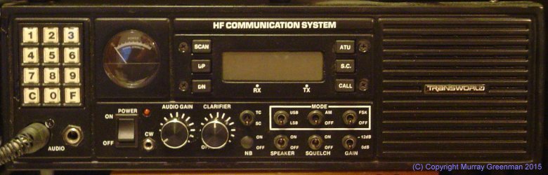
The Transworld TW100
Kenwood TKM-707 (1989)
Designed at a time when Amateur receivers and transceivers contained a mass of circuit boards with connectors and wires everywhere, the TKM-707, built to a completely different requirement, is deceptively simple inside. There are only two boards - the receiver and exciter, and the PA assembly. Unfortunately mine is missing the latter, so it is essentially a receiver with +10 dBm output capability. I have had to replicate some of the functions on the missing PA assembly, such as +10V regulated supply and antenna switching. But when you look inside the cover, the contrast of the simple design to the average complicated ham rig is startling! Yet the result is a high-performance, reliable transceiver with commercial use specifications. One of the secrets to the apparent simplicity is the use of thick-film hybrid devices.The TKM-707 uses a 71.3 MHz first IF with a monolythic roofing filter, and a 10.695 MHz second IF with a single crystal filter. The synthesizer generates both injection oscillators via different loops. The transceiver does not operate LSB or CW: only A3J (USB) and A3H (compatible AM). There is no RF gain control, and the AGC is always fast. However the transceiver is ideal for digital mode operation, and it is in 24 hour service on 40 metres at present.
Nominally a marine transceiver, there are internal switches and links that will allow the user to set the operating frequency from the front panel, and/or program the memories. With these changes the transceiver will operate anywhere using the main tuning knob. The receiver incorporates excellent syllabic squelch. In the top right corner of the front panel is a small hinged cover which hides lesser used controls and a full numeric keypad. The transceiver is very stable, as it incorporates a simple OCXO reference for all oscillators. It operates from 1.6 to 23 MHz, and will receive from 500 kHz to 30 MHz. Power is external 13.8V, and the unit is quite light (especially without the PA!). The case is sheet Aluminium, with a robust plastic moulded front panel over a heavy Aluminium sub-panel. The dimensions are 270 x 96 x 270 mm.
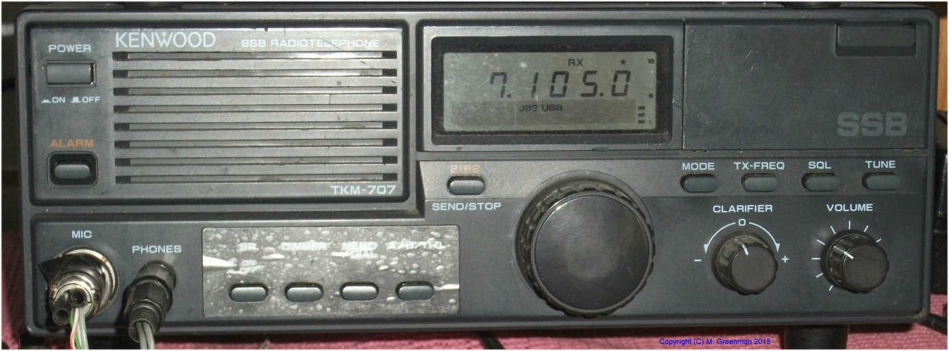
The Kenwood TKM-707