My Receiver Collection
24 May 2019
Introduction
1920s - 1950s
1960s
1970s
1980s
1990 - today
Introduction - the 1960s
In this era valve designs were phased out, but some of the solid state designs could not compete with the better tube radios.
It was also a time of marked changes in mechanical design, although some of the receivers were not ergonomically sensible.
Drake 2B (1961)
When it was first released, the Drake 2B caused quite a stir, and quickly became very popular. The performance is excellent, and the stability is remarkable for a valve receiver. Great care went into the PTO VFO design to provide maximum stability, and it is more
stable than many newer receivers. This is the oldest of my Drake receivers.
The receiver (which cost me $50) required only minor repair and an exterior clean-up. It gave the appearance of having been home to mice
at some point, but despite this, the interior and copper-plated chassis are clean, and it operates really well. I also have the Heathkit
after-market crystal calibrator fitted, and own a Codar RQ10 Q Multiplier designed for use with the 2B.
The 2B has a dial-cord operated slide-rule dial, but isn't as good as that in the old Eddystones. It feels light and has some
backlash in the pointer (but not the tuning). There are 10 valves, and the arrangement is triple conversion, with a crystal-switched
first conversion, a tunable 3500 - 4100 kHz first IF, 455 kHz second IF and 50 kHz third IF. The receiver has passband tuning in the
third IF, which is very effective, and three bandwidths, 0.5, 2.1 and 3.6 kHz.
SSB reception is excellent, and stability is unbelievably good for a modestly priced valve receiver of that vintage.
The 2B is nominally ham-bands only, with 600 kHz range on each of 12 bands between 3.5 and 30 MHz. The receiver uses a preselector,
and by judicious fiddling, you can achieve reverse tuning on some additional frequency ranges. My 2B is 110V operated.
The receiver is quite small - dimensions are 300 x 220 x 180 mm. It weighs 6.6 kg.
Tube lineup: 6BZ6, 6U8, 6BE6 x3, 6BA6, 6BF6, 8BN8, 6AQ5, 6X4.
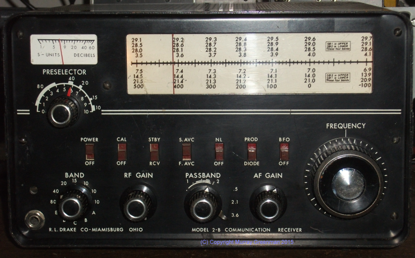
The Drake 2B
Plessey PR152 (1962)
Without question the oldest of my solid-state receivers, the Plessey PR152 is also one I know very little about. It uses PNP Germanium transistors,
OC171 in the front end, and many GET535 devices elsewhere. From what I understand, it is double conversion, with a 1.6 MHz first IF and 480 kHz second IF. There is a 1100 kHz crystal oscillator. The second IF coils are
double-tuned, giving a slightly double-humped passband, which I have measured to be 7.5 kHz wide at the 3dB points, and about 13 kHz at 30dB down.
Coverage is 550 kHz to 30 MHz in six bands. There's no preselector, but the antenna trim is quite sharp, which combined with the use of Litz-wound
coils give the impression of good front-end selectivity. While more a 'short wave radio' rather than a communications receiver, performance is
fairly good, even up at 30 MHz. Stability and AM audio are good. There's no product detector (which is sad, as SSB had been around
for some time in 1962), and although CW reception is reasonable, SSB is pretty tricky. You don't really have single-signal reception because of
the wide IF, and the tuning rate is a bit fast, so tuning in SSB is best done with the BFO control. There is just one IF bandwidth, but there is
a really sharp audio filter for CW reception, unusual for a 'short wave radio'. It is centred on 1 kHz and is about 100 Hz wide at the 3dB points,
600 Hz at -30dB.
Given the age of the radio, and that it uses Germanium transistors, the sensitivity is remarkable. I measured about 3uV for 10dB SNR on all
bands, and slightly better toward the top end of each band. That's very good considering the broad IF.
The assembly consists of a conventional chassis with a main circuit board beneath (IF, filter and audio), while the tuner and bandswitch assembly
is off to one side, incorporating other small circuit boards, with the tuning gang next to it. The battery eliminator sits on the chassis behind the tuning mechanism. Almost every wire
in the radio is PINK, making tracing circuitry a challenge! The front panel is a simple flat Aluminium anodized plate with silk-screened black text, over a steel front panel. The case is a large machined Aluminium casting. Construction is very sturdy.
The most remarkable feature of this receiver is the tuning mechanism. It features a 70mm film-strip dial (equivalent to six metres long!),
and a 70mm diameter tuning drum which is driven by direct and planetary drive knurled wheels to the right of the drum. The drum drives the
tuning capacitor via a worm-drive with anti-backlash gears. The tuning mechanism has a sturdy cast Aluminium frame, with bronze bearing
inserts, and tuning is smooth and easy,
with no backlash. The bandspread is impressive. There's a further concentric wheel to the left of the drum which moves the dial pointer
to provide localized calibration, although it seldom needs tweaking as the calibration is good. (The set has a 1 MHz and 200 kHz crystal calibrator).
Nominally a 9V battery operated set, my PR152 is fitted with a 230V 'battery eliminator', which makes life convenient. Because it is designed for
battery operation, power consumption is low (about 50mA at 9V, peaking at 100 mA with full audio) and there are no panel, meter, or tuning dial lights.
Audio quality is excellent, and there is a good-sized speaker in the left side.
Believe me, you'll find nothing on the internet about this receiver, apart from a press release in Wireless World Feb 1963, which says:
"Plessey Communications receiver type PR152 is a compact all-transistor model covering the m.f. band (550-1500 kc/s) and the h.f. band (1.65-30 Mc/s) with a film-scale tuning system giving a total effective scale length of 18ft."
As you'll see from the photographs, this rare receiver is in remarkably fine condition for its age. Everything is original, right down to the
unusual bathtub-shaped knobs. The rear RF connector is a UHF (SO239) type.
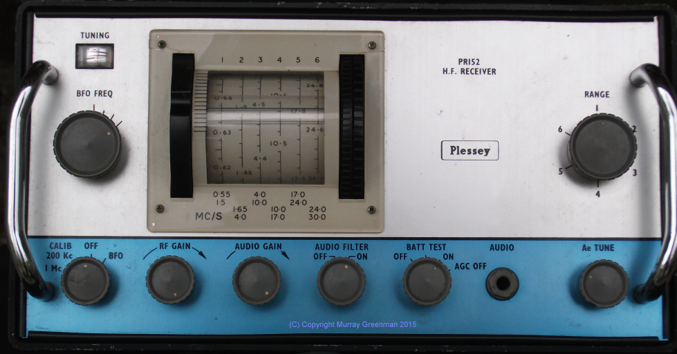

The Plessey PR152 (left),
rear view with tuning mechanism (right)
JRC NRD1050 G (1963)
Made right at the end of the valve receiver era, this Japan Radio Company receiver is a robust marine receiver of high quality and
very conservative design. The case includes a cubical skeleton frame of welded nickel-plated steel, with six heavy anodised Aluminium
outer panels. The top and bottom panels have removable clip-in covers to allow access. Internal structures, the chassis and shields,
are Aluminium.
The receiver has 15 miniature tubes (B7G and B9A), including a voltage regulator, all labelled. All the tubes have metal covers.
The outside of the receiver looks a little tired, and there is minor corrosion, but internally the receiver looks like new,
and there is no obvious damage apart from a few unspecified modifications. The receiver dimensions are 400 x 220 mm, and 340 mm deep.
It weighs about 15 kg.
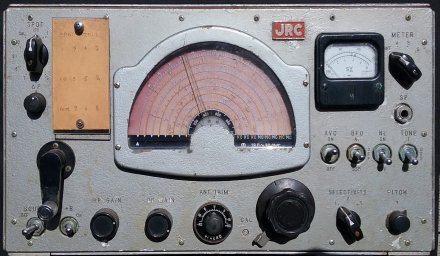
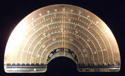
The JRC NRD 1050 front panel (left),
and detail of the dial scales at night (right)
The receiver is single conversion, with an IF of 575 kHz, and operates on eight bands from 90 kHz to 30 MHz. There are two mechanical filters to provide selectivity, and two RF amplifiers with associated tracked preselector coils to provide reasonable image and
out-of-band rejection. The TONE switch offers two reduced audio bandwidths.
The tuning dial is a conventional semi-circular type, with individual calibration for each band. It uses a side-lit rear engraved
acrylic dial. Below the dial is a narrow horizontal drum which rotates with the band switch to indicate which band is active.
The band switch is a 'crank handle' on the left, which operates the band indicating drum and a conventional band switch via
a gear arrangement.
The bands are:
- 90 - 220 kHz
- 220 - 530 kHz
- 590 - 1600 kHz
- 1.6 - 4 MHz
- 4 - 7 MHz
- 7 - 12 MHz
- 12 - 19 MHz
- 19 - 30 MHz
To provide reliable calibration, the receiver is fitted with a bank of crystals which can be used to spot check and trim the receiver
frequency. There's also a band-spread control (probably a fine tune control) marked in increments to � 10 kHz, which is concentric
with an antenna trim capacitor.
The power supply is external, 6.3 V AC and 250 V DC (I don't have the original supply). The receiver operates very well, with
accurate calibration, and smooth tuning. There is a little hum, which I'll fix in time. I've not been able to find
any documentation for this receiver, so all I know has been discovered by observation and reverse engineering.
If you have any information regarding this excellent old receiver, please let me know.
Eddystone EC10 Mk 1 (1968)
This is Eddystone's first solid state receiver. It's really interesting to compare this receiver with the slightly older Plessey PR152 shown immediately above.
It's very obvious that the Eddystone has good looks, and has
a classic Eddystone appearance. It is ergonomically well designed as well. The Plessey is in contrast fairly utilitarian, and while the film-strip dial has far better accuracy and band-spread than the Eddystone, it is not as easy to tune around with vertical edge-tuned knobs. The other big difference is in performance: the Eddystone is
fairly modest, lets say, while the Plessey is quite impressive for its age.
The EC10 is a single conversion short wave listener's receiver with a 465 kHz IF, and a fixed IF bandwidth, suitable for AM. It includes a BFO, although
performance on SSB is quite poor. It's not so much actually resolving SSB, but that the receiver pulls quite badly as a result of AGC action. It is best
with the AGC off, controlling the signal with the RF Gain, and then SSB is reasonably intelligible.
The receiver covers 550 kHz to 30 MHz, continuously in five bands. Bandspread is reasonable up to about 10 MHz, although the calibration accuracy is modest.
The level of audio distortion is not up to modern standards, and probably comes from the diode detector.
The EC10 is well constructed, with the RF board at the bottom, and the IF/Audio board inverted at the top (see picture links below).
Access is quite good, as the IF board can be rotated and secured, giving access to both sides and to the top of the RF board.
The OC170 RF amplifier is arranged in common base, and there are two double-tuned IF amplifiers with AGC. While there is a 465 kHz trap at the antenna,
IF breakthough can be a problem, and above 8 MHz, image rejection is modest at best. There is an effective 1 kHz audio filter for CW reception.
My EC10 is fitted with the 'battery eliminator', which screws into the back panel. The wiring is rather lethal - you would not want to take the mains supply
off or remove the folded steel case with power applied, as the AC connector terminals are then exposed. Power consumption is quite low, about 50 mA,
which doubles when you activate the panel lights. The lamps are only on while you hold down the button, making the dial markings
adequately visible in the dark.
The dial is similar to those of earlier Eddystone receivers, a large 'slide rule' type glass dial with very clear graduations, the pointer and tuning
gang driven by a dial cord. There is no slack or backlash in the tuning, so operation is a pleasant experience. There is a 0 - 500 logging scale, and
a fine logging scale above the weighted tuning knob, which allows you to interpolate the reading. The logging scale is useful because the dial calibration on most bands is fairly vague! Another point of difference with the Plessey, which has impressive dial accuracy and resolution.
The EC10 Mk1 version has no 'S' meter and no fine tune control. The Mk2 version has both, with the fine
tune control replacing the headphone socket, which moves to the rear. Both lack an antenna fine tune, a calibrator (which I suggest would be essential),
and neither have a means to measure the battery (the Plessey has all these).
My EC10 example goes very well, is really clean inside and out, and has few scratches on the case. No restoration has been required,
although a realignment would probably be beneficial. I have added a short lead with a BNC connector to
suppliment the horrible antenna connectors supplied. These aren't standard banana socket sized, and work best with a stripped wire end and a match to jam
it in! Both low impedance and high (short whip) inputs are offered.
The receiver weighs about 6.5 kg (much lighter than the die-cast Plessey PR152), and is quite a bit smaller than the older (valve) model Eddystones,
just 320 mm long, 162 mm high and 200 mm deep.
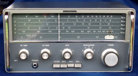
The Eddystone EC10 Mk 1
Norlin SR-219 (1965?)
This is a surveillance receiver from the mid 1960s. I don't know much about it, except the IF is 21.4 MHz, and it uses plug-in heads to provide
coverage from 3 MHz to 7 GHz. There were several variants with different IF bandwidths. I have two heads, covering 30 to 100
MHz (SH-201P-1) and 90 to 300 MHz (SH-202P-1), and I have borrowed and checked it with other tuners. The receiver
operates FM, AM, CW and PAM. It has nice tuning and signal strength meters. A pretty receiver, with no speaker output, only headphones and a rear
line connection.
Reception of FM broadcast is fairly good, and that of Amateur and commercial NBFM transmissions is adequate, but lack of squelch is a problem.
These two lowest-frequency tuner heads have an amazing planar spiral variable inductor mechanism in the ganged tuning, and all versions have a rear-lit film-strip dial and beautiful anti-backlash gearing.
The design and construction of this receiver is of the highest quality. It has plug-in boards with gold-plated connections. The larger SR-209
receiver uses two of the same plug-ins, and has is a 'panadaptor' option.
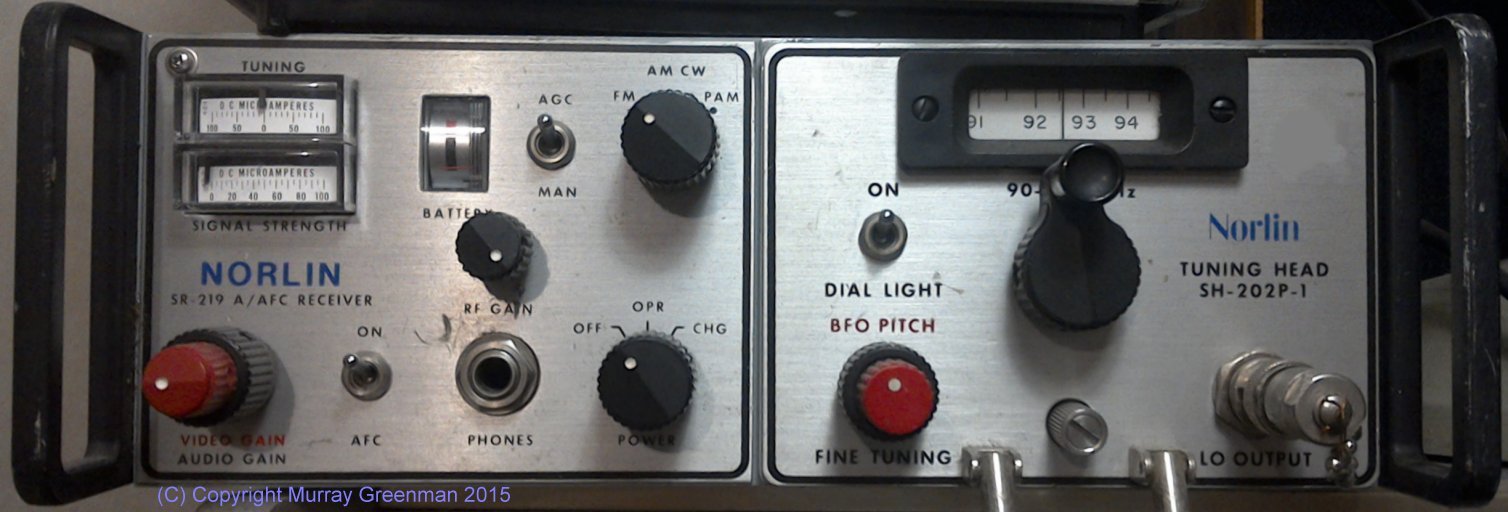
The Norlin SR-219 with 90 - 300 MHz plugin
Redifon R499 (1969)
This receiver is a solid-state single-conversion fixed-frequency type intended for commercial installations.
It was manufactured between 1969 and 1972, was widely used for marine radio applications, and is rack mounted and configured for remote control.
It will operate AM, SSB, DSB, CW, or ISB, depending on
the options fitted. It has a maximum of 10 channels, on MF or HF. 1ppm stability is provided by a crystal oven.
Separate crystals and front end filters are required for each channel.
Frequency coverage is from 1.5 to 30 MHz, but with special MF filters can also operate from 225 to 525 kHz.
The IF frequency is nominally 1.4 MHz. There is a fine
tune control with an approximate range of 100 Hz. The receiver will operate from 100-125V, 200-250V AC or 24V DC, and weighs 10 kg.
My R499 is not operating, as it lacks the front-end filters and crystals. Since these were plug-in items, toward the end of
the useful life of these receivers, it appears that parts were robbed from some receivers to keep other receivers going.
These receivers had a great reputation for reliability and bullet-proof performance.
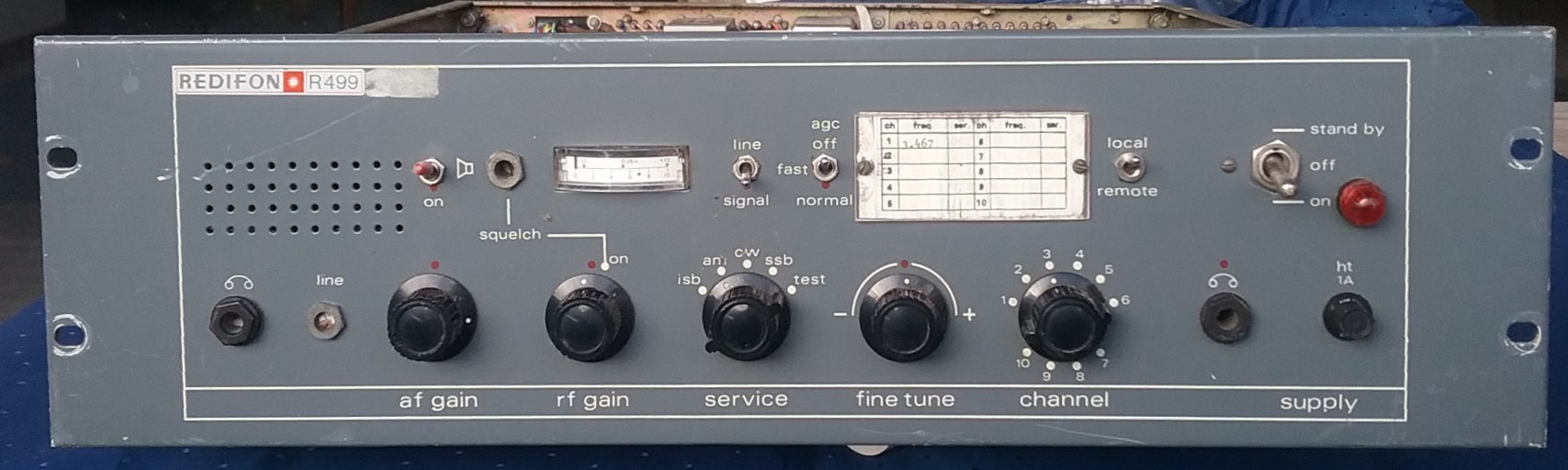
The fixed-channel Redifon R499.
AWA Teleradio ONE (mid 1960s)
This unit was designed and made in New Zealand. It was manufactured by AWA in their Adelaide Road factory (Wellington). It is an early solid-state radio designed for NZ Search and Rescue, and transmits and receives AM. Many of these sets were also purchased by the Mountain Radio Service.
It operates
on two HF channels, 5680 kHz and 4922 kHz. The unit has an IF of 455 kHz, and uses ceramic filters. The crystals fitted confirm this,
and that the channels were for simplex use.
In 1974, the NZ Post Office ruled that only SSB radios could now be manufactured for use on HF in New Zealand, and existing AM radios
were to be phased out by 1980.
It was replaced by the TR3 (see below) and later the SSB model TR105 (late 1970s), popularly called the 'butter box' (it was also yellow). I understand that Vern Lill ZL2TMI was closely involved with the design of the Teleradio One.
He was also involved in setting up the Mountain Radio Service.
Vern was also the designer of the 'Wellington Walkie' VHF hand-held radio. It had one feature in common with the Teleradio One - it used a
telephone earpiece as the speaker/microphone.

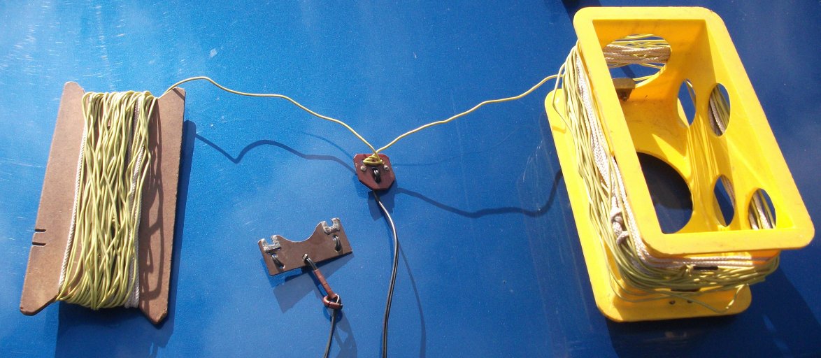
The AWA Teleradio One (left),
The cradle with antenna wound on it (right). Note the
balanced feedline and phenolic fittings. The fibreboard winder is probably not original.
The transceiver (without batteries) weighs just 882g, and is 185 mm long, 100mm wide and 110 mm deep.
The front-panel dynamic microphone also acts as a speaker. The unit operates from eight AA cells, which
mount inside a waterproof hatch on the front. The contruction is moderately waterproof, with a rubber gasket between the front and the case,
which has instructions for use printed on it. It also has a Kiwi 'New Zealand Made' logo on the side, which is puzzling, as my research
shows that this trademark dates from 1986. It may be that there was informal use much earlier.
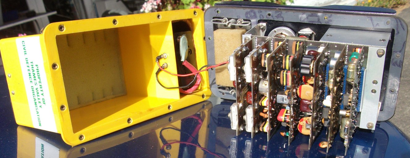
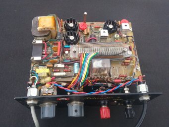
Inside view of the AWA Teleradio One.
Note the battery compartment in the case.
The two left-most boards in the above picture carry the channel crystals and tuning components. The next two boards are the receiver RF and IF,
then the transmitter, modulator, and audio section.
The transmitter ran about 1 Watt.
The antenna feed cable is a
balanced pair, about 3.5m long. The outward ends of the antenna wires are terminated in braided nylon cord, with no formal insulators.
Its previous owner was the Thames Valley Civil Defence Organization.
AWA Teleradio 3 (late 1960s)
This unit was also designed and made in New Zealand by AWA. It was an improved solid-state AM radio designed for NZ Search and Rescue.
These sets were also purchased by the Mountain Radio Service, including the ones I have, serial numbers 6, 40 and 83. Superficially
the unit is single-channel (5680 kHz), although the internal design allows for two channels. The transceiver is fully waterproof.
The transceiver is a single-conversion Germanium transistor design with an IF of 455 kHz, using a TOKO mechanical filter. The transmitter was conventional,
using four 2N1613 transistors: oscillator, buffer, and two in parallel in the output stage. The transmitter ran 1W output.
The radio ran off eight D cells (rather better endurance than the AA cells of the Teleradio ONE), which were housed in a separate
waterproof interchangeable box. These days a set of eight D cells would set you back $25 or so - and you can buy a Chinese VHF
FM transceiver for only twice this much!
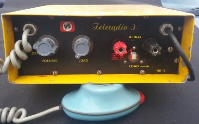
The AWA Teleradio 3 (left),
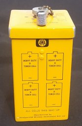
The battery box (right).
The transceiver (without battery pack) weighs 1858 g, and is 200 mm wide, 80mm high and 190 mm deep. The case is Aluminium.
The battery pack is also Aluminium, and weighs 1482 g with cells fitted.
The waterproof dynamic microphone is on a fixed curly cord, and also acts as the speaker.
The yellow-painted case has operating instructions printed on the top, and the Phonetic Alphabet printed on the bottom.
There are just two operating controls: a VOLUME control (with power switch), and a transmitter LOAD control, which switches
taps on the PA stage Pi-coupler output coil. Power output is adjusted by peaking a tiny meter, operated by a current transformer
and detector at the output.
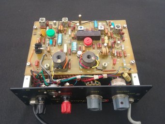
Inside view of the AWA Teleradio 3 (top, receiver).
Inside view of the AWA Teleradio 3 (bottom, transmitter).
Introduction
1920s - 1950s
1960s
1970s
1980s
1990 - today
Copyright � Murray Greenman 1997-2019.
All rights reserved. Contact the author before using any of this material.