![]()
![]()
![]()
![]()
![]()
![]()
![]()
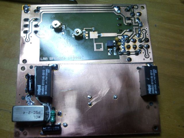
BFG135a
BJT by Infineon
NEW!
FOR ALL HF BANDS 1-30 MHz
Output IP3 is over +35 dBm at all HF bands !
Noise Factor NF:
2 to 2.5 dB!
Gain S21: from 19 dB to 23 dB.
Unconditional stability K>1, B1>0
1-30 MHz (zip)


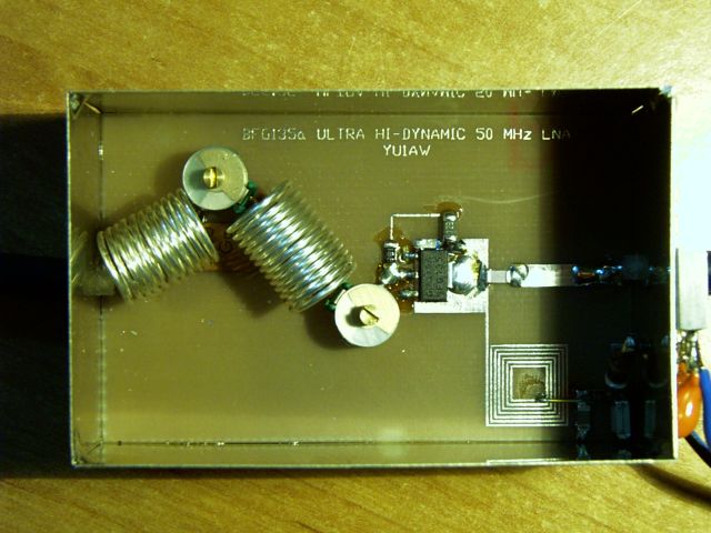
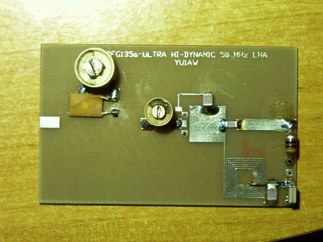
FOR 50 MHz BAND
Input IP3: around +16 dBm !
Output IP3 : around +39 dBm !
Noise Factor NF:
around 2 dB! 
Gain S21: around 23 dB.
50 MHz (zip)

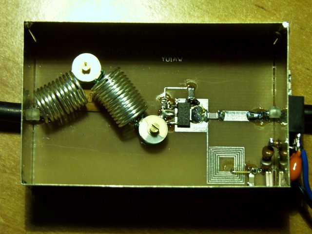
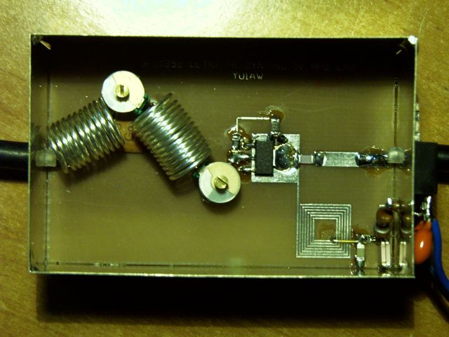
Built by Greg, SP3RNZ
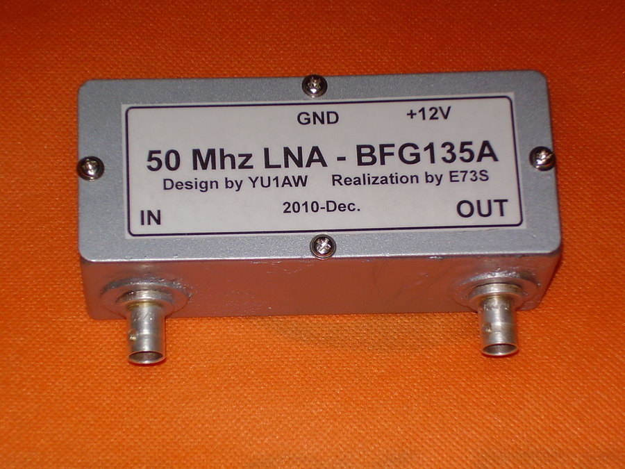
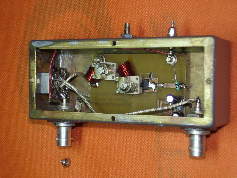
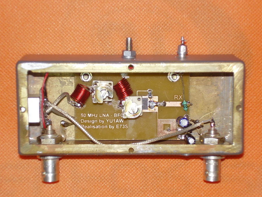
Built by Zoran, E73S
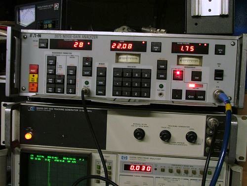
Measurements results of 6m preamplifier:
BFG135a_6m_measur_by_WA7TZY.pdf Build by Fred, WA7TZY
NEW!
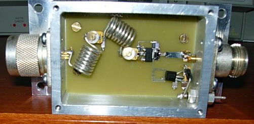
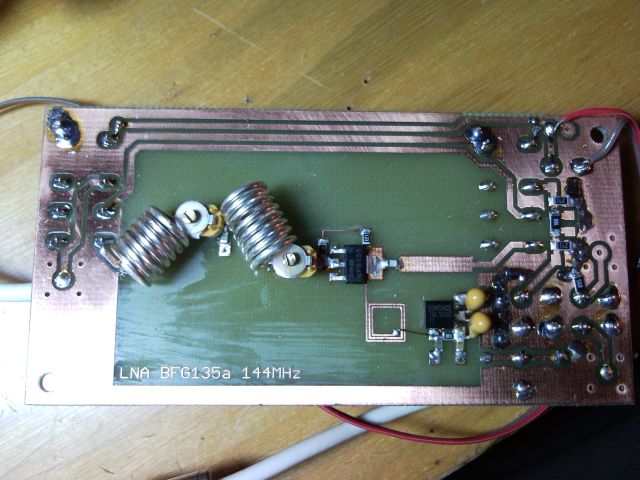
FOR 144MHz BAND
Input IP3: from +17 dBm to +19 dBm !
![]()
Output IP3 : from +37 dBm to +39 dBm !
Noise Factor NF:
2 to 2.2 dB! ![]()
Gain S21: from 20 dB to 23 dB.
144 MHz (zip)

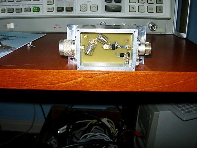
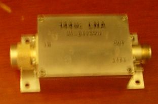
Built by: Palle, OZ8AFC
Built by: Josef, OK1TKP -http://josefkrieglstein.trenet.cz/?q=node/34
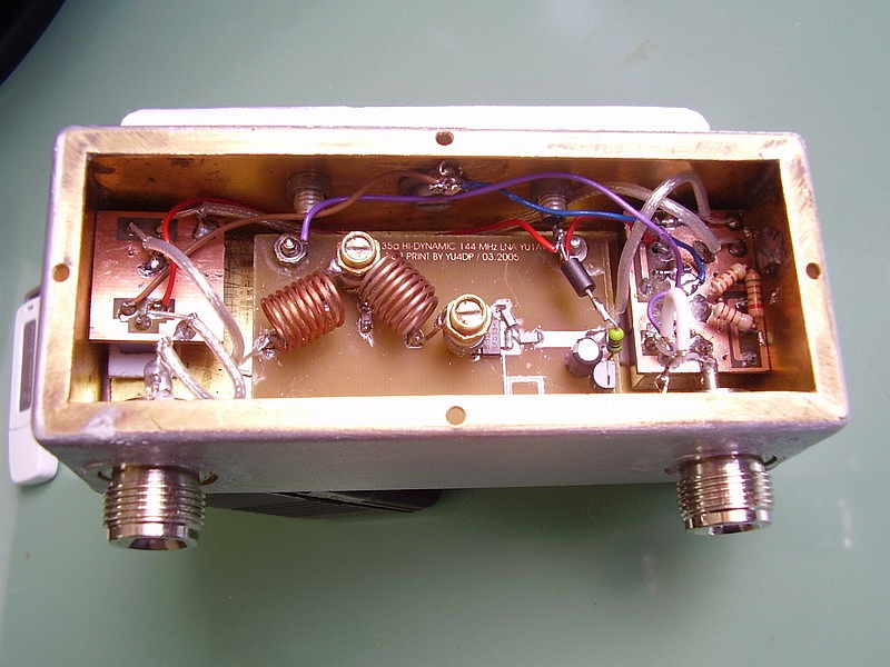
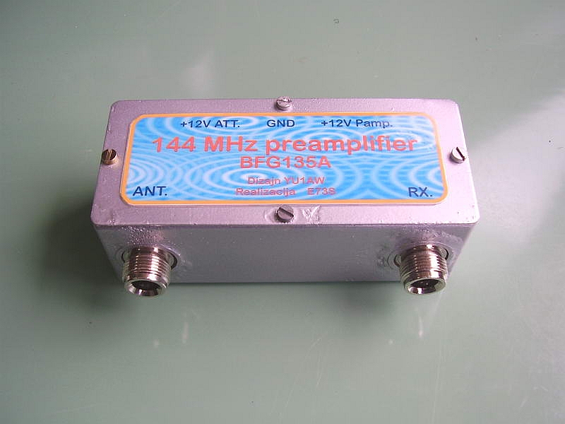
Built by: Zoran, E73S
WIDE BAND FOR HIGHER HF AND LOWER VHF BANDS
From 14 MHz to 70 MHz :
Input IP3: from +17 dBm to +23 dBm !
![]()
![]()
![]()
![]()
Output IP3 : from +39 dBm to +42 dBm !
Noise Factor NF:
2.5 to 3.0 dB!
![]()
Gain S21: from 16 dB to 23 dB.
WB 10-70 MHz (zip)
FOR HIGHER HF BANDS
From 21 MHz to 28 MHz :
Input IP3: from +18 dBm to +19 dBm !
![]()
![]()
Output IP3 : from +39 dBm to +41 dBm !
Noise Factor NF:
2 to 2.5 dB! ![]()
Gain S21: from 20 dB to 23 dB.
21-28 MHz (zip)
![]()
Built by Hans, DK1NB
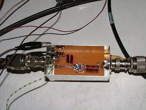
Built and measured by: Anto, IK4PMB
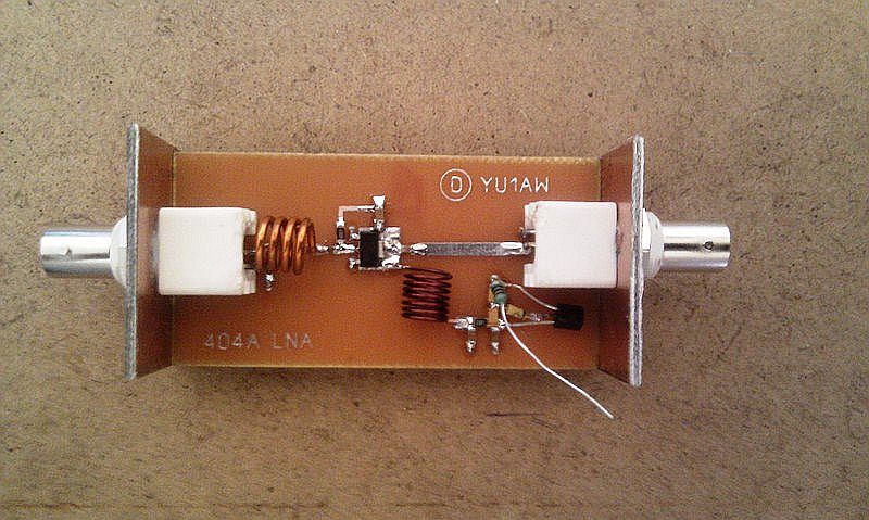
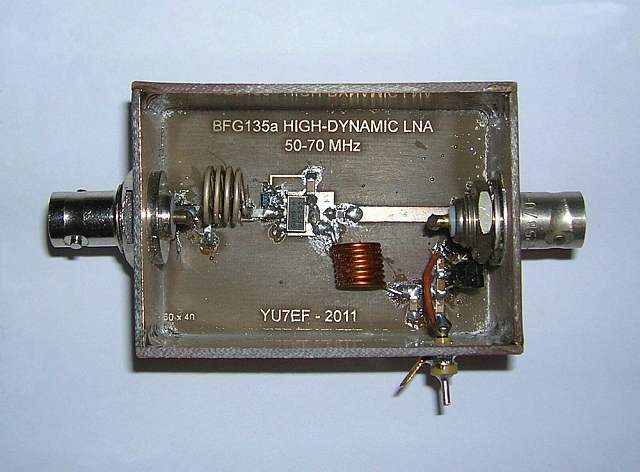
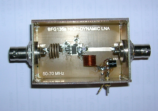
FOR LOWER VHF BANDS
From 50 MHz to 70 MHz :
Input IP3: from +18 dBm to +19 dBm !
![]()
![]()
Output IP3 : from +39 dBm to +40 dBm !
Noise Factor NF:
2 to 2.2 dB!
![]()
Gain S21: from 20 dB to 23 dB.
50-70 MHz (zip)

Built by Alessandro IK0VAQ


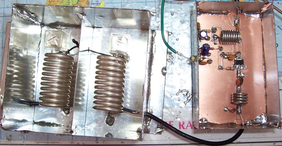
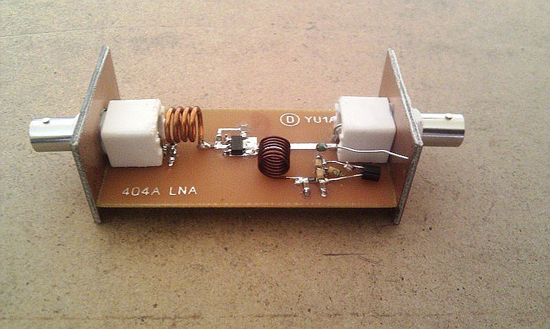
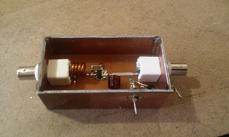
Built by Dragan, 4O4A

Built by Popa, YU7EF
Atention!
Do NOT mix BFG135a produced by Infineon (former Siemens),
with BFG135 produced by Philips! They are different types of transistors and they have different IMD!
In these preamplifiers use only BFG135a by Infineon!
AutoCAD files in DWG format for Printed Circuit Boards:
BFG135a 144 MHz - PCB BFG135a 1-30 MHz - PCB
BFG135a WB 10-70 MHz - PCB BFG135a 21-28 MHz - PCB BFG135a 50-70 MHz - PCB
All PCBs made of 1.6 mm double side FR4 or G10 epoxy (Er=4.8). Back side left as ground plane.
All used SMD components are type 1206.
AutoCAD files in DXF format for Printed Circuit Boards:
BFG135a 144 MHz - DXF BFG135a 1-30 MHz - DXF
BFG135a WB 10-70 MHz - DXF BFG135a 21-28 MHz - DXF BFG135a 50-70 MHz - DXF
"Three Strong 6m Stations" Working Test
In order to check how amplifiers will behave in DX work and contests I conducted some simulations. BFG135a amplifier was fed with three strong signals ("three strong stations on 6m band") 7.1 mV (-30dBm) each, at its input. Output spectrum given below, showing what would be heard with ideal, linear receiver (no receiver IMD!) under such conditions, and very obvious IMD superiority of BFG135a preamplifier.
![]()
![]()
![]()
![]()
![]()
![]()
![]()
![]()


