VARIOUS DIGITAL SAMPLING STEREO CODERS |
The following examples are intended for hobbyists interested in building "oversampling" stereo coders. This web page contains information only for educational purpose!
The most important parameters of digital stereo coders are sampling rate and number of bits used to generate 38KHz L-R subcarrier. A high sampling rate is preferred, as it reduce harmonic content and makes MPX signal easier to filter. High-order filters should not be used to clean the MPX channel due to phase response issues. Sampling stereo coders are frequently manufactured because they offer a good S/N ratio, excellent dynamic range, stable operation, and low harmonic distorsion. Unfortunately, reliable information on this subject is difficult to find, so I will attempt to share my own experiments with several stereo coder designs.
Another important aspect to consider is the the behiavour of digital switching modulators. The resulting 38KHz DSBSC (Double Sideband Suppressed Carrier) component (SUB L-R) has a mplitude approximately π/4 times higher than normal, and L / R crosstalk correction is required. Otherwise the stereo component will appear excessively "wide" compared to the original program material (to so-called "hole-in-the-middle" effect). This correction is no longer necessary when the modulator can better approximate a sinewave (using more steps and a higher sampling rate).
Crosstalk correction is often applied even in professional 8x...14x stereo coders. The circuit injects a fraction of the L and R signals into the MPX summing amplifier to ballance the MAIN (L+R) and SUB (L-R) components. Another method involves injecting of L -> R and R -> L prior to the DSBSC switching modulator inputs. These adjustments are commonly referred to as crosstalk, suppression or R-L / L-R.
![]() 1. Katruud (or similar schematic) 8X stereo coder
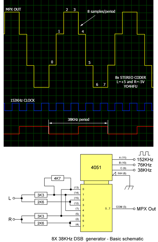
1. Katruud (or similar schematic) 8X stereo coder
8x oversampling DSB generator with 4051 multiplexer. During simulation, Left and Right audio channels were connected to +5V/-5V.
Frequency of clock signal 152KHz.
.
![]() 2. CD4067 16X digital DSB generator
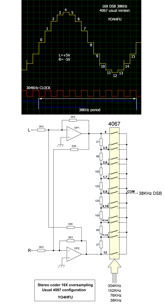
2. CD4067 16X digital DSB generator
Below, other 16X oversampled DSB generator with 4067. This version is frequently posted over Internet. Usually 4067 is supplied with +/-7,5V.
Clock signal necessary for 16X at 38KHz is 304KHz. Input operational amplifiers were not used during simulation.
![]() 3. David III 16X Stereo Generator
3. David III 16X Stereo Generator
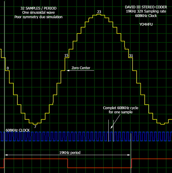
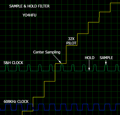
Now one example of sampling technique using 608KHz clock, but in this case is generated sinusoidal 19KHz pilot tone.
32 samplings per period are performed for pilot tone. Entire 608KHz pulse is necessary for one sample step. DSB 38KHz multiplexer working in same mode, but with 16x oversampling and 608KHz clock.
For more details read “Inovonics David III 718 FM Stereo Processor/Generator”, can be downloaded from Internet. Digital block built up with 4028/4029/4051 CMOS integrated circuits, differential power supply for 40xx circuits (+/-9V ?) and interesting digital logic was implemented.
Update 26.11.2016: David III Clone was tested with very good results! Please check my page: DAVID III Stereo Coder.
Update 13.12.2016: In the next image, Zero Center is wrong. Correct position of zero line is with one step above, at 15 and 31 level. Symmetry is poor due simulation.
Sometimes, digital synthesis of 38KHz subcarrier and 19KHz pilot is succeeded by "Sample & Hold" filtering. Digital noise generated during switching resistor taps can be eliminated. After S&H circuit, a simple LC low pass filter is required.
In the next image, both DSB and Pilot signals are filtered at 608KHz. Switches SW1,2 are turned ON for one-half of one clock cycle at the center of each stepped pilot waveform sample. This charge 330pF capacitor to the sample voltage value, which is held by operational buffer until next center sample is taken. Center sampling eliminates integration of switching noise that is concurrent with leading/trailing edges of the waveform steps.
![]() 4. DB ELETTRONICA TELECOMUNICAZIONI PM1000 SERIES
4. DB ELETTRONICA TELECOMUNICAZIONI PM1000 SERIES
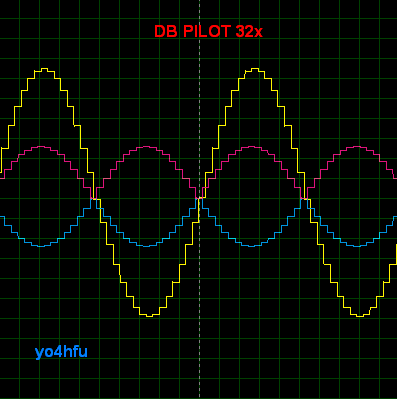
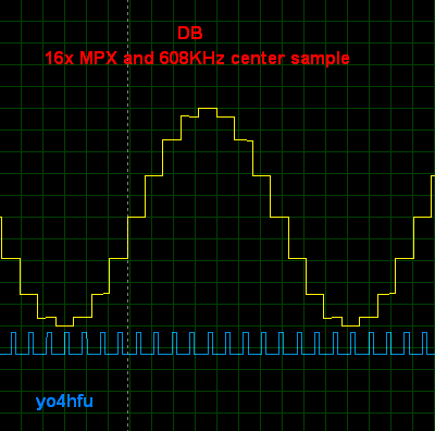
Pilot tone 19KHz is composed from 16 digital steps, inverted and after combined in order to result 32 steps full "sine". Pilot tone and MPX are cleand by S&H at 608KHz. Resistors R13 and R15 are used to adjust 19KHz symmetry / null crossover.
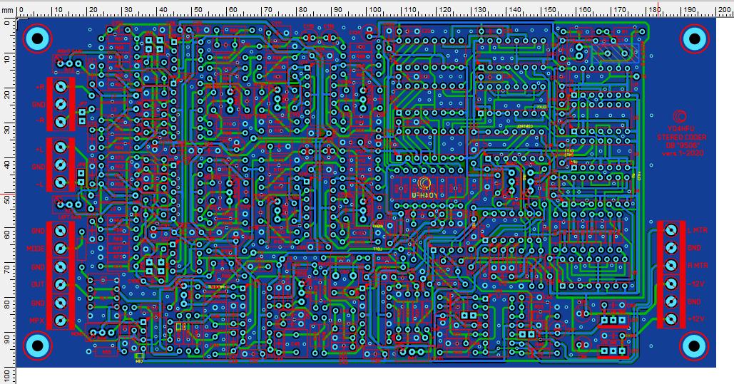
PM1000 exciter is very interesting and I intend to build entire stereo coder type "9506". Audio 15KHz elliptical LPF is same with Inovonics 705/715/718 or ETG RVR. MPX 38KHz generator use 8 precision resistors to obtain 16x oversampling.
Also DB KE20 FM exciter use same stereo coder.
Update 13.01.2025: DB9506 Home made clone completed, very good results!
![]() 5. Rohde & Schwarz NU002-B exciter, similar 14X Phatom FM stereo coder
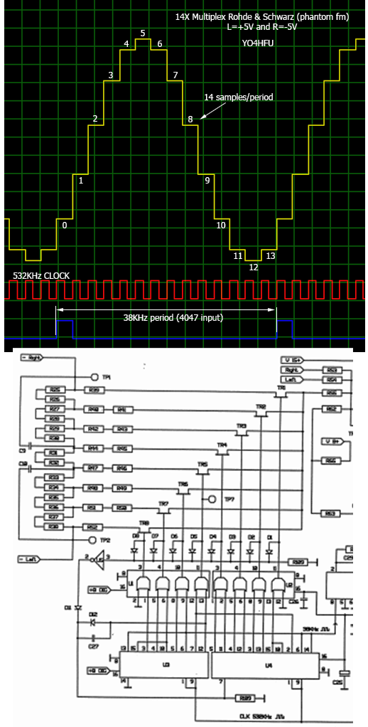
5. Rohde & Schwarz NU002-B exciter, similar 14X Phatom FM stereo coder
Simulation of R&S professional stereo coder 14x oversampled. Switching performed with FETs BSR56 (BF245C) and 4015 counters. Clock signal: 532KHz.
![]()
![]() Rohde & Schwarz NU002-B
Rohde & Schwarz NU002-B
![]() Phantom FM 14x Stereo Coder 1998
Phantom FM 14x Stereo Coder 1998
![]() 6. CTC30 Stereo Coder
6. CTC30 Stereo Coder
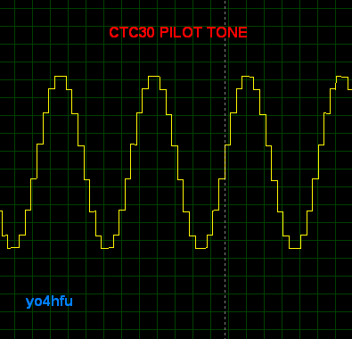
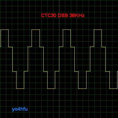
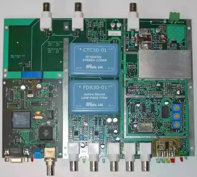
Stereo coder module used inside of professional RVR SDC100 stereo/RDS coder, Elettronika PLL-CS or Elettronika Mira250S FM exciters. DSB/Pilot generator is similar with unknown Kathrein stereo exciter.
Sampling rates are 8x DSB and 16x PILOT. CTC30 & Katruud 8x are using same design for 38KHz DSB generator. As a rule 4.864MHz or 2.432MHz quartz oscillator is required for clock.
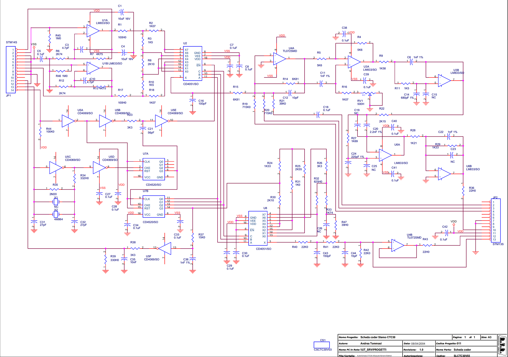
Note: JP2 connector equivalence between internal schematic and application note Pin 1 = 27, Pin 13 = 15.
Update 31.01.2025: take a look to RVR TEX150LCD/S service manual. Same SLCTC30V3 stereo coder board. 15KHz low pass filters are almost the same as Inovonics and DB PMxxx series.
![]()
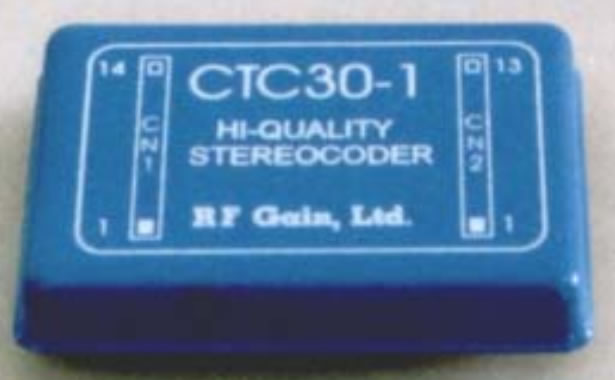
![]() CTC30-1 datasheet
CTC30-1 datasheet
![]() CTC30-1 internal schematic diagram (SLTCTC30V03 board RVR PTX30...150LCD series)
CTC30-1 internal schematic diagram (SLTCTC30V03 board RVR PTX30...150LCD series)
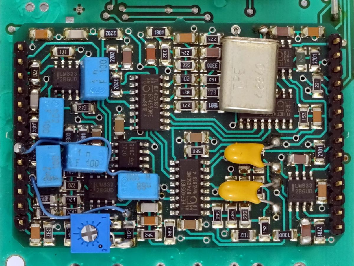
![]() SLTCTC30V03 components
SLTCTC30V03 components
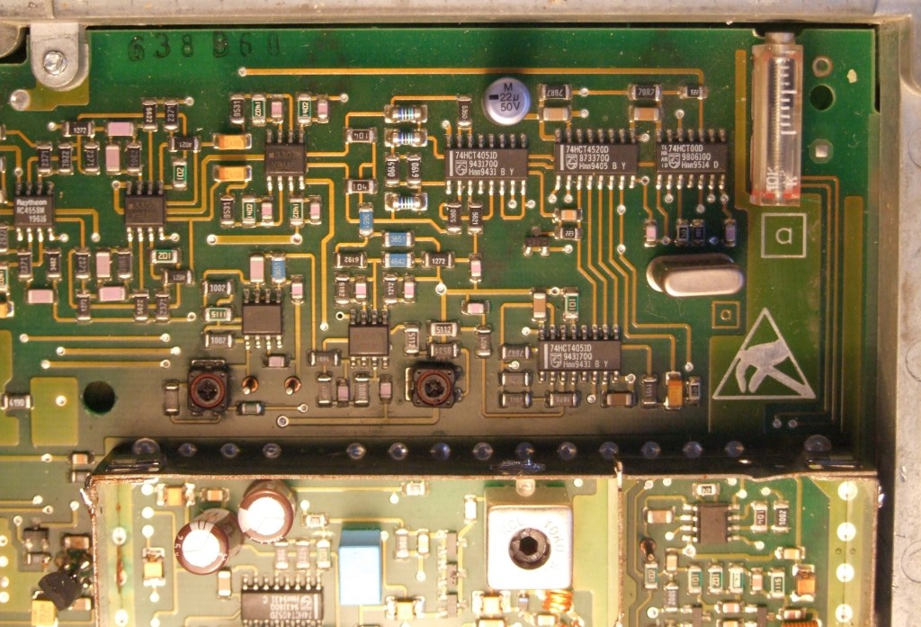
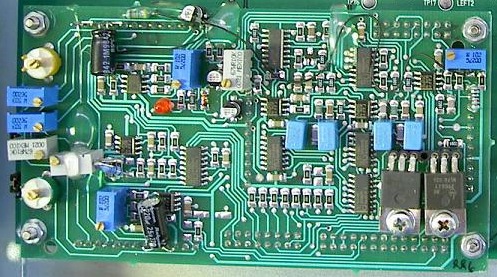
![]() CTC30-1 internal view
CTC30-1 internal view
![]() SDC100 stereo coder schematic, view of SDC100 PCB (CTC30 located under board), similar RVR main board.
SDC100 stereo coder schematic, view of SDC100 PCB (CTC30 located under board), similar RVR main board.
![]() Elettronika PLL-CS MPX schematic and internal view
Elettronika PLL-CS MPX schematic and internal view
![]() Elettronika MIRA250S service manual
Elettronika MIRA250S service manual
![]() RVR TEX150LCD/S - full schematic stereo coder & 15KHz low pass filters (RV1 & RV6 = notch 35.5KHz, RV2 & RV7 = notch 19.3KHz, RV3 & RV8 = notch 22.3KHz. According RVR PTX series service manual)
RVR TEX150LCD/S - full schematic stereo coder & 15KHz low pass filters (RV1 & RV6 = notch 35.5KHz, RV2 & RV7 = notch 19.3KHz, RV3 & RV8 = notch 22.3KHz. According RVR PTX series service manual)
![]() 7. BEXT XT150S
7. BEXT XT150S
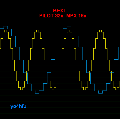
Bext XT150/S service manual reveals 2 versions for stereo coder option:
- 1st version SDC30 use 4053 CMOS switches and 4015 shift registers. Adjustement resistors: P3-Balance 38KHz, P4-19KHz phase, P5-level 19KHz external output, P6- level 19KHz pilot. Pilot tone is generated at 32x and MPX 16x oversampled. The schematic diagram is simple and can be easy duplicated at home. Mono/Stereo switch and External MPX switches can be removed. Commun RST line 4015 must to be connect to GND for stereo operation. Q1 FET is neccesary only for Mono/Stereo switching. IC20A removed, IC20B bypassed if Left External MPX input is not required. Power supply is simple rail +15V, virtual ground +7.5V simulated by IC3B. 15KHz Pasive LPF AF1...AF4 can be replaced by other LPF topology. IC18, IC19 LM393 are not required.
- 2nd version SDC30A002 use IRV30CT (CTC30) stereo coder module (SM page 136). Same schematic inside of RVR-BEXT TEX100 FM Exciter.
MPX Clipper built with CA3096.
![]()
![]() BEXT 150 Stereo Coder Schematic vers.1
BEXT 150 Stereo Coder Schematic vers.1
![]() BEXT XT150S FM Exciter - Service Manual
BEXT XT150S FM Exciter - Service Manual
![]() 8. BLUES 30 RVR and ETG INDIUM ELENOS
8. BLUES 30 RVR and ETG INDIUM ELENOS
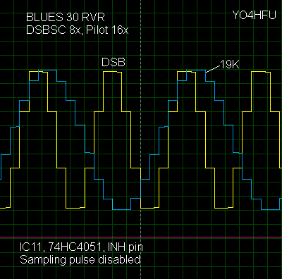
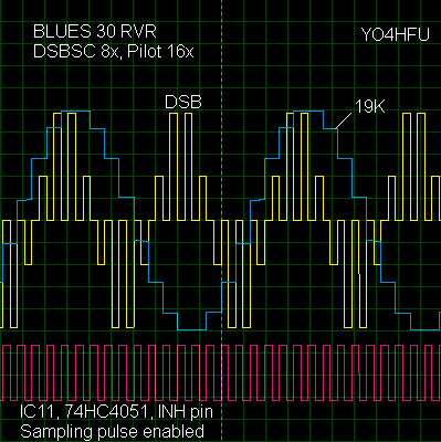
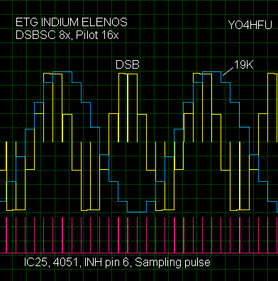
Both FM exciters use a similar stereo coder section built around 4520 counters and 4051 switches. The clock frequency is 4.864MHz. DSBSC modulator works at 8x, while the pilot tone is generated at 16x. In order to correct the SUB and MAIN components (due to DSBSC amplitude error), channels L and R are injected into the MPX summing amplifier. Summing levels are adjustable for optimal L and R suppression. A 38KHz null adjustment is also available by offsetting the modulator.
Another similar feature is the rejection of leading/trailing edges of the waveform steps,achieved by inhibition the DSBSC 4051 modulator during the beginning or the end of each switching step. Note that the BLUES 30 schematic diagram contains a mistake: the clock logic is incorrect (same as shown on the PCB in the service manual). It should be also nothed that the BLUES 30 MPX filter looks more complex than the ETG one.
![]() BLUES 30 RVR - corrected schematic
BLUES 30 RVR - corrected schematic
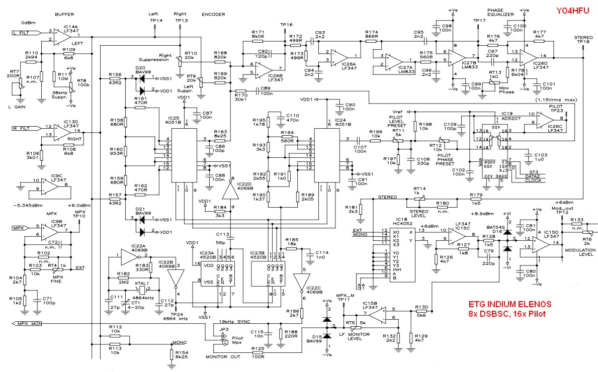
![]() ETG INDIUM Series ELENOS - schematic
ETG INDIUM Series ELENOS - schematic
However, see the service manuals for more details.
![]()
![]() BLUES 30 RVR - Service Manual
BLUES 30 RVR - Service Manual
![]() ELENOS ETG150/300 INDIUM - Service Manual
ELENOS ETG150/300 INDIUM - Service Manual
![]() 9. ELCA XPT / VIMESA XPT / CTE TX / T.E.M. "Blue Star"
9. ELCA XPT / VIMESA XPT / CTE TX / T.E.M. "Blue Star"
Stereo encoder module "DMPX" found in transmitters made by various manufacturers.
Investigation in progress...
![]()
![]() VIMESA / CTE DMPX - Service manual
VIMESA / CTE DMPX - Service manual
![]() 10. Stereo Coder controlled by Walsh function
10. Stereo Coder controlled by Walsh function
![]()
![]() Russian Walsh StereoCoder - received from Toomas S. 2018
Russian Walsh StereoCoder - received from Toomas S. 2018
Pilot tone Walsh 8x filtered by LC tank. MPX is oversampled at 4x (2 levels).
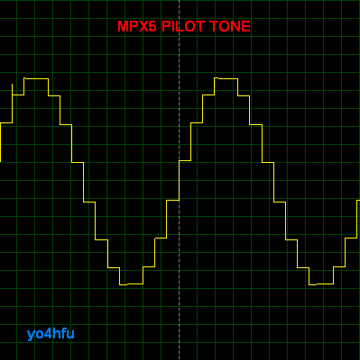
![]() SBS FM30 (SBS MPX5) Stereo Exciter - Eddystone Broadcast
SBS FM30 (SBS MPX5) Stereo Exciter - Eddystone Broadcast
Pilot tone 16x and MPX 8x oversampled. Walsh sequence generated by 4060/XOR 74HC86. The exciter is similar with TX 150/300 Broadcast Warehouse or TX5 FM BW Broadcast which are controlled by PIC uC . Pilot tone generator use only 4 resistors switched according Walsh function. Proteus simulation reveals exactly same waveforms compared with CTC30, but using less number of resistors!
![]() 12. Other stereo coders
12. Other stereo coders
![]() FM-25 Stereo Exciter - Broadcasting Solution Electronics
FM-25 Stereo Exciter - Broadcasting Solution Electronics
Square wave 19KHz is generated by 74HC4520 clocked at 38KHz and then active bandpass filtered (square / sine conversion), pilot tone THD<0.1%. MPX 16x derived from 74HC4015/74HC32/74HC74/ 2 x 74HC4316 and 7 resistors. Main 532KHz clock signal is obtained by 74HC4520 from 4.256MHz quartz oscillator. Left / Right audio Elliptical LPFs have similar topology with Inovonics / DB Electronica.
![]() CONCLUSIONS
CONCLUSIONS
Simple 4066 stereo coders are not recommend because chopped waveform has sharp edges so it will have a lot of odd harmonics. These extraneous harmonics dirty up the signal. Also the SUB component amplitude (38KHz L-R) is not equal with MAIN (L+R), the level of SUB is π/4 higher than normal and L / R crosstalk correction is required, otherwise the stereo component will be more "wide" than original program ("hole in the middle" effect).
Extra energy in the wrong place means that we waste transmitter power and we also limit the maximum modulation deviation for the signals we really want to transmit. Reduction of harmonic content can be observed when weighted oversampling technique is used.
Conclusion after various stereo coders were compared: high performance units have MPX 16x oversample, pilot tone 32x oversample (or narrow active 19KHz BPF) and posibility to adjust symmetry, harmonic null.
Do not forget:
1. A phase shift in the Audio MPX Chain causes loss of Channel Separation.
2. A change in gain over the 0-53 KHz region will negatively affect the Channel Separation.
3. MPX signal can't be processed (limit, pre-emphasis or compress). All the audio processing should have been done before the MPX process. Is possible to use soft MPX clipper only to keep maximum deviation less than +/-75KHz.
4. Hard limit process generate distortions (harmonics)! MPX clipper is sometimes called "safety clipper". Always the pilot signal must to be injected after MPX clipper.
5. Use TX exciters with good linearity of frequency modulation.
6. Audio input signal must to be pre-emphasis (50/75uS) and sharp 15KHz low pass filtered (brickwall filter). Audio filter needs to perform good 19KHz attenuation, in order to avoid any interference between audio program and 19KHz pilot tone.
All low pass filters exhibit a certain amount of overshoot and ringing when presented with complex input waveforms. Some techniques can be used to compensate overshoot effect. Left and right channels need to be adjusted for same gain/phase performances.
7. Choose monitor FM receiver with good performances regarding channel separation and S/N ratio. In this way is possible to make correct adjustments of stereo coder.
8. It's recommended to set high output level of stereo coder and adjust lower sensitivity on the exciter, rather than set low output level and adjust high sensitivity of the exciter.
![]()
![]() MISCELLANEOUS SCHEMATICS
MISCELLANEOUS SCHEMATICS
![]()
![]() 15KHz active LPF Katruud
15KHz active LPF Katruud
![]() 15KHz Low Pass Filter with pre-emphasis
15KHz Low Pass Filter with pre-emphasis
![]() 15KHz LPF - Sprint Layout PCB
15KHz LPF - Sprint Layout PCB
![]() 15KHz active LPF Rohde & Schwartz NU002-B
15KHz active LPF Rohde & Schwartz NU002-B
![]() R&S Audio Section
R&S Audio Section
![]() PLL clock oscillator
PLL clock oscillator
Universal solution to drive digital stereo coders using 4,332MHz resonator. Clock signals are generated by 4046 VCO/Phase comparator - PLL. Main oscillator uses a 4,332MHz crystal, very easy to find in any FM receiver with RDS decoder.
In this way is possible to avoid necessity of special crystal, hard to find. Square wave available output frequencies: 19, 38, 76, 152, 304, 608KHz.
![]() PLL clock oscillator Schematic
PLL clock oscillator Schematic
![]() PLL clock oscillator PCB
PLL clock oscillator PCB
![]()
![]() FM STEREO BROADCASTING EQUIPMENTS - SCHEMATICS COLLECTED FROM INTERNET.
FM STEREO BROADCASTING EQUIPMENTS - SCHEMATICS COLLECTED FROM INTERNET.
***PLEASE SEND ME ANY OTHER INTERESTING INFO ABOUT STEREO CODERS***
![]()
![]() INOVONICS DAVID III 718 (Stereo Coder) - INTERNAL VIEW - PCB TOP / BOTTOM (tnx to Tajera!)
INOVONICS DAVID III 718 (Stereo Coder) - INTERNAL VIEW - PCB TOP / BOTTOM (tnx to Tajera!)
![]() INOVONICS DAVID II 716 (Stereo Coder)
INOVONICS DAVID II 716 (Stereo Coder)
![]() INOVONICS DAVID I 715 (Stereo Coder) - read Calibration Chapter
INOVONICS DAVID I 715 (Stereo Coder) - read Calibration Chapter
![]() INOVONICS 708 (Stereo Coder)
INOVONICS 708 (Stereo Coder)
![]() INOVONICS 705 (Stereo Coder)
INOVONICS 705 (Stereo Coder)
![]() PM300 DB ELETTRONICA (Stereo Exciter) - schematic mistakes, internal photo
PM300 DB ELETTRONICA (Stereo Exciter) - schematic mistakes, internal photo
![]() PM1000 DB ELETTRONICA (Stereo Exciter)
PM1000 DB ELETTRONICA (Stereo Exciter)
![]() R&S NU002-B (Stereo Coder section)
R&S NU002-B (Stereo Coder section)
![]() RVR SDC20 (Stereo Coder)
RVR SDC20 (Stereo Coder)
![]() RVR SDC100 (RDS/Stereo Coder)
RVR SDC100 (RDS/Stereo Coder)
![]() RVR TEX150LCD/S (Stereo Exciter)
RVR TEX150LCD/S (Stereo Exciter)
![]() RVR BLUES 30 (Stereo Exciter)
RVR BLUES 30 (Stereo Exciter)
![]() ELETTRONIKA PLL-CS (Stereo Exciter)
ELETTRONIKA PLL-CS (Stereo Exciter)
![]() ELLETTRONIKA MIRA250S (Stereo Exciter)
ELLETTRONIKA MIRA250S (Stereo Exciter)
![]() BROADCASTING SOLUTION ELECTRONICS FM-25 (Stereo Exciter)
BROADCASTING SOLUTION ELECTRONICS FM-25 (Stereo Exciter)
![]() BROADCASTING SOLUTION ELECTRONICS FM-100 (Stereo Exciter)
BROADCASTING SOLUTION ELECTRONICS FM-100 (Stereo Exciter)
![]() ELENOS ELC40 (Stereo Exciter)
ELENOS ELC40 (Stereo Exciter)
![]() ELENOS ETG150/300 INDIUM (Stereo Transmitter)
ELENOS ETG150/300 INDIUM (Stereo Transmitter)
![]() ELENOS ETG SERIES STEREO CODER OPT - interesting, similar LPF and overshoot compensation as Inovonics 718
ELENOS ETG SERIES STEREO CODER OPT - interesting, similar LPF and overshoot compensation as Inovonics 718
![]() INOVONICS 531(N) (Modulation Analyzer)
INOVONICS 531(N) (Modulation Analyzer)
![]() INOVONICS 260 (Audio Processor)
INOVONICS 260 (Audio Processor)
![]() EDDYSTONE BROADCAST SBS FM-30 (Stereo Exciter)
EDDYSTONE BROADCAST SBS FM-30 (Stereo Exciter)
![]() BROADCAST WAREHOUSE TX 150/300 (Stereo Exciter)
BROADCAST WAREHOUSE TX 150/300 (Stereo Exciter)
![]() BW BROADCAST TX5 FM (Stereo Exciter)
BW BROADCAST TX5 FM (Stereo Exciter)
![]() BEXT XT150/XT150S FM Exciter (Stereo Exciter)
BEXT XT150/XT150S FM Exciter (Stereo Exciter)
![]() VIMESA XPT-50, CTE TX250S (Stereo Transmitter) - DMPX Board
VIMESA XPT-50, CTE TX250S (Stereo Transmitter) - DMPX Board