DB 9506 STEREO CODER CLONE |
DB Elettronica Stereo Coder "9506"
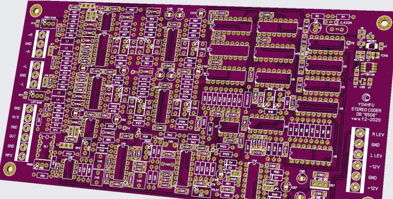
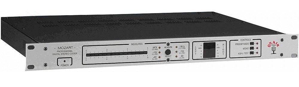
Being fascinated about digital stereo coders, I decided to build a replica (clone) of this professional design which has been used over time in various equipments from the same company, such as the KE-20 FM Exciter, FM transmitter PMxxx series, Mozart Digital Stereo Coder, and the new Mozart FM Exciters (and maybe more). This stereo coder PCB is also known as Stereo Encoder 9506-01, designed June 1995. It is a compact stereo coder that includes elliptic LPF and the audio frontend. It uses digital oversampling technique, 32x for the pilot and 16x for the DSB subcarrier.
To clarify, replicating the stereo coder block was purely a curiosity for myself, without any commercial intent. I still have a few PCBs available if you're interested. Feel free to reach out! I can only ship to the EU. Anyway, the Gerber files are available for free in the download section.
The project was based on an extensive study of service manuals from various manufacturers with similar designs. The primary reference was the DB PM1000 service manual, which included schematics and component placement. From there, I routed the PCB using Sprint Layout (5 years ago), an intricate process given that I didn’t have access to the original PCB, only a low resolution photo. Over time, additional photos of this stereo coder appeared online, allowing me to refine my understanding of its operation and specific details. The cheap production of custom PCBs from China made me to revive this project.
The new DB Mozart FM Exciters use the same design, albeit with some modern updates. Certain trim pots have been replaced with digital potentiometers or DACs, enabling microcontroller based adjustments.
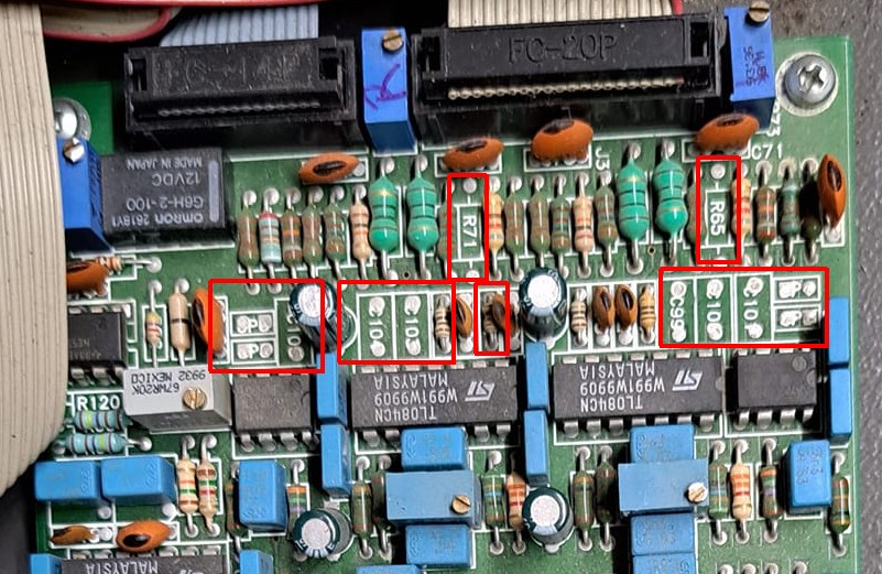
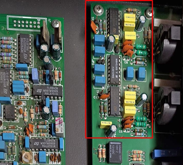
For the DB Mozart Digital Stereo Coder variant, the audio input circuit (pre-emphasis and RC high-pass filter) has been relocated to a separate board, and these components are absent on the main 9506-01 PCB. Additionally, 15KHz phase equalization has been removed from the main PCB (capacitors C127, C50) and trimmer R37 being replaced with a fixed 1k resistor, stage relocated on the same IN/OUT board.
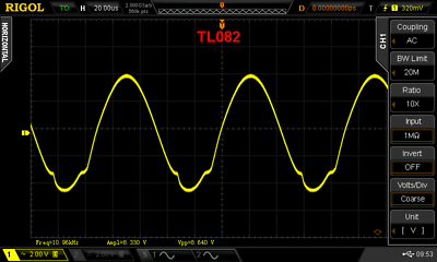
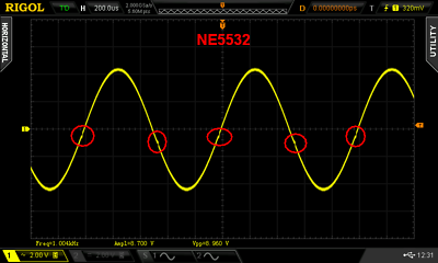
It’s worth emphasizing the importance of using high-quality components with tight tolerances. Resistors should be 1%, and capacitors should be 2.5% or better, especially around the elliptic filter on the L and R channels. Pay extra attention to operational amplifiers; use only from reliable source. I encountered issues with TL082 and NE5532 chips purchased from eBay, despite the seller’s positive reviews. Counterfeit OA can lead to crossover distortion or other anomalies, so if these phenomena appear on the oscilloscope, it’s likely due to counterfeit IC amplifier.
When possible, I adhered to the components specified in the service manual. Interestingly, the Mozart Digital Stereo Coder uses only TL084/082 (instead of MC33079/NE5532), likely due to cost considerations.
I included additional test points and the option to insert a limiter (clipper) immediately after the pre-emphasis circuit, similar to the Mozart Next series.
The 2.432MHz quartz oscillator was replaced with an SI5351/Attiny25 and 27MHz 0.5ppm TCXO. While such precision isn’t strictly necessary (19KHz ±2Hz is acceptable), the TCXO solution proved exceptionally stability and accuracy, achieving 19KHz ±0.01Hz.
The quartz version can also be used, the PCB is designed to accommodate both options.
Online discussions indicate that certain DB stereo coders generate a pilot tone that is insufficiently filtered, potentially causing unwanted parasitic modulation of the transmitter carrier. This conclusion is entirely false, 19KHz filtering is properly designed, but DB stereo coder can exhibit this issue due to a heavy distorted pilot signal.
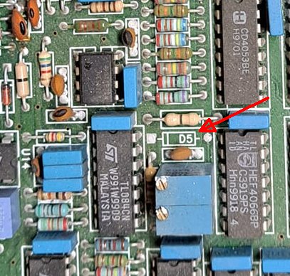
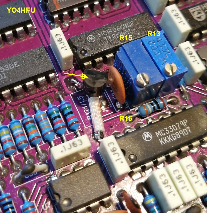
The root cause is poor adjustment of the symmetry circuit related to 19KHz sine wave generator. This circuit is sensitive to component aging and variations in the negative supply rail. A drift of -12V ±0.2V or minor changes in component values (especially trimmer R15) can lead to misalignment. In certain models, such as the Mozart Digital Stereo Coder, D5 zener diode is not installed, despite appearing in certain service manuals, so "bias" current is not very stable. Properly adjusted, the 19kHz sinusoidal pilot signal is exceptionally clean, without carrier spurious modulation! I will return with more details about the correct adjustment of the pilot signal, measurements, and how to fix the drift.
The alignment presented another challenge, as the service manual did not provide explicit instructions for adjustment process.
![]() Adjustments points:
Adjustments points:
C9 - 2.432MHz frequency adjustment (not used)
C60 - Pilot phase (also C129)
R13 - 19KHz Polarity level symmetry (SYM)
R15 - 19KHz Sine shape symmetry (BIAS)
R37 - 15KHz separation
R41 - Pilot level
R45 - MPX output level
R56 - Mono level
R73/R72 - Right/Left gain
R80/R102 - 34570Hz notch
R82/104 - 19110Hz notch
R83/R106 - 21780Hz notch
![]() 19KHz ADJUSTEMENT
19KHz ADJUSTEMENT
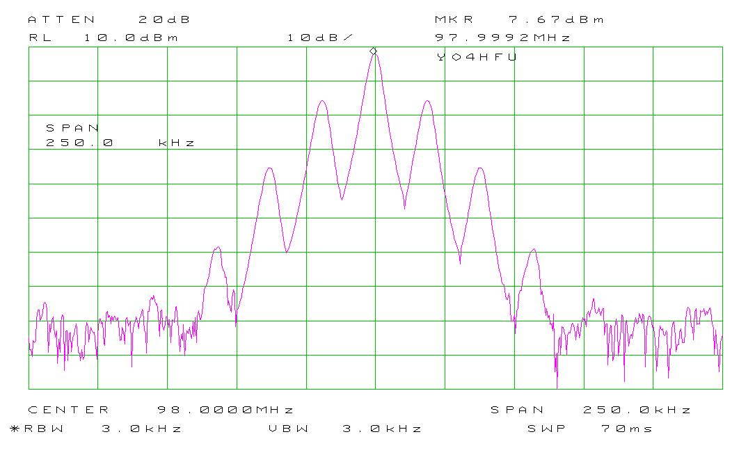
The best way to adjust 19KHz "BIAS" R15, symmetry "SYM" R13 is to inject the MPX signal to FM excitter and to monitor carrier side-bands (span 0.5...1MHz).
Test done on a dummy load. Don't apply any audio program. The adjustment is difficult / not very accurate using oscilloscope.
1. The BEXT TX 20 FM exciter producing a non-modulated carrier.
However, the carrier is not extremely clean, meaning better results cannot be achieved even when an MPX signal will be injected.
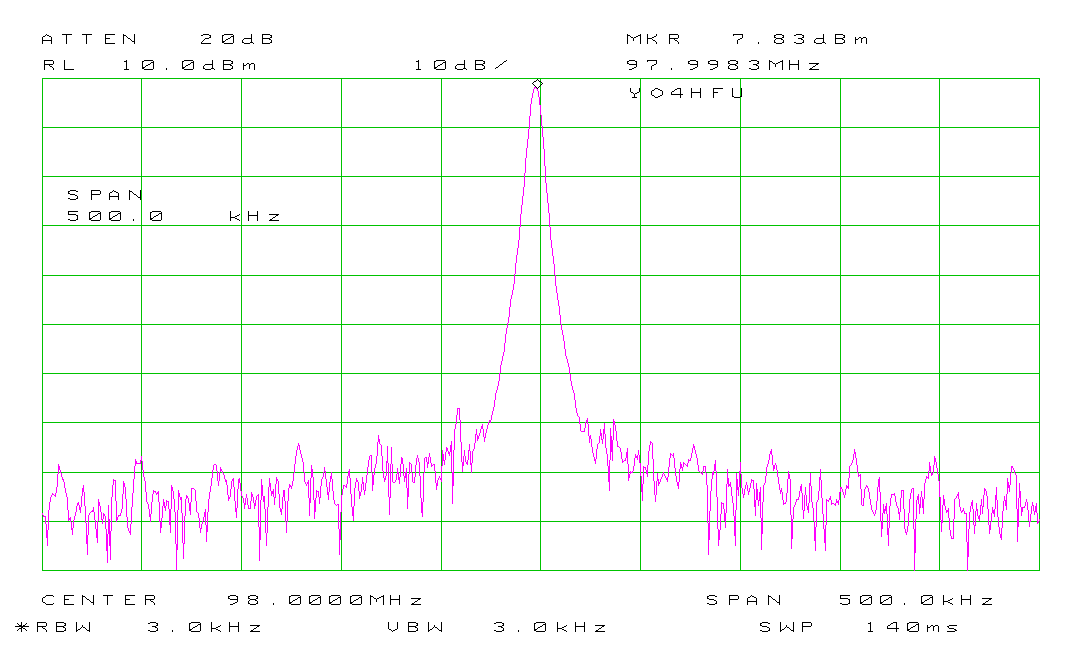
2. The exciter is modulated with a pure 19 KHz sinewave generated by an HP33120A Function Generator. The pilot level is not important, just to have an comfortable view.
This test serves as a reference for the next measurements — check the level of high-order sidebands
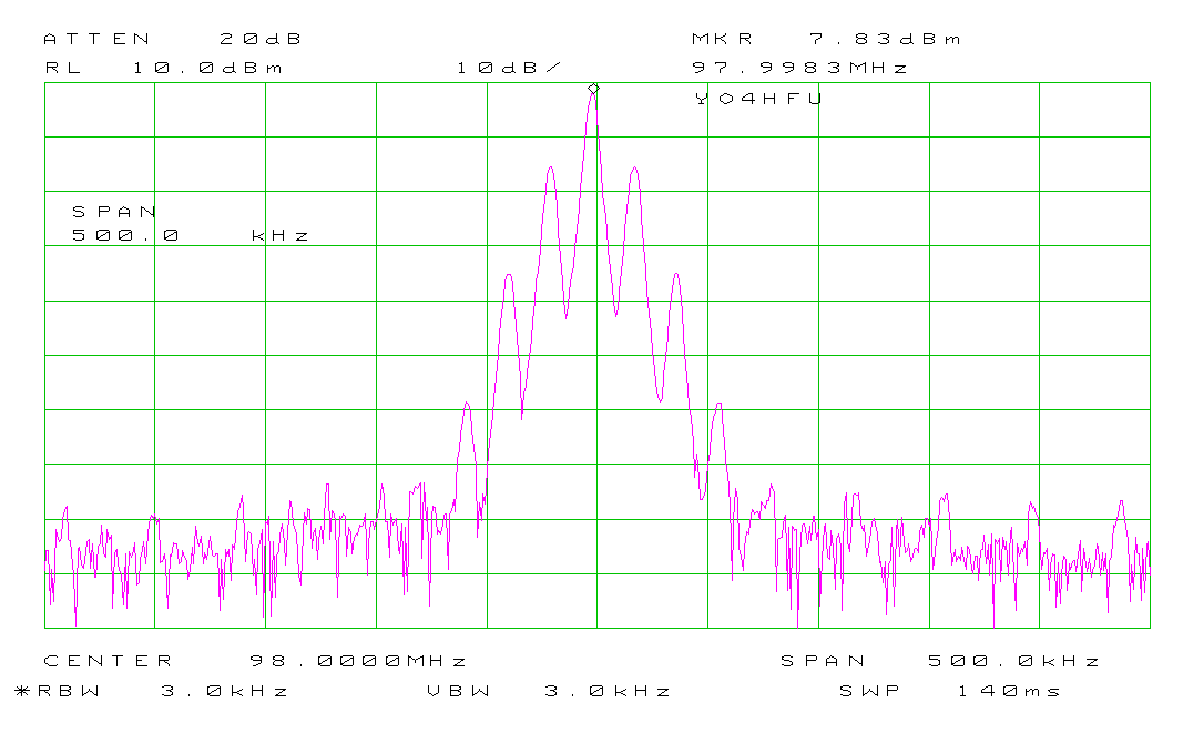
3. The DB9506 MPX output is injected into the exciter's MPX input. The R15 'BIAS' is incorrectly adjusted. The pilot level is set to match the second-order sidebands from the previous reference test.
As observed, high-order sidebands appear due to the distorted sinewave pilot.
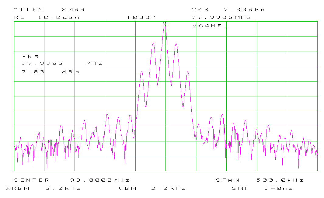
4. With R15 'BIAS' correctly adjusted for minimum level of high order side-bands. The carrier now appears identical as HP 33120A reference test (Step 2). The DB9506's pilot tone is a perfect sinewave.
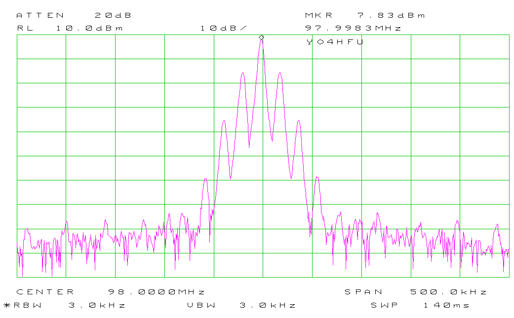
5. With R13 'SYM' incorrectly adjusted, the lower and upper sidebands have different levels.
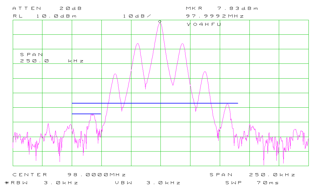
6. With R13 'SYM' correctly adjusted, the carrier is symmetrically modulated by the pilot tone.
![]() 19KHz GENERATOR SECTION - HOW TO FIX THE DRIFT
19KHz GENERATOR SECTION - HOW TO FIX THE DRIFT
As mentioned earlier, the circuit that synthesizes the 19 kHz sinusoidal pilot tone has been reported to become unstable over time, likely due to power supply drift or the aging of components, particularly R15.
The negative voltage from the -12V rail must be very well stabilized. The service manual is not very clear on this aspect, but the original PCB seems to be designed for additional stabilization using the Zener diode D5 and the limiting resistor R121.
However, the schematic differs: the D5 Zener diode is missing (replaced with a 220nF capacitor), and resistor R121 is replaced with a 10µH inductor. In the DB Mozart stereo coder, the D5 diode is absent, and R121 is replaced with a 0-ohm jumper.
Tests have shown that the D5 diode should be 10V. Using an 8...9V Zener diode will require modifications to R15, R16, and even R14 (in the case of 8V). A Zener diode higher than 10V will no longer provide sufficient stabilization when the supply voltage is between 11.5...12.5V. Therefore, 10V is a perfectly acceptable compromise. Resistor R121 should be around 82 ohms, with the diode's load current being approximately 10mA. This setup offers good stability when the -12V voltage stays within ±0.2V. Thermal stability is acceptable.
However, for very good stability, I opted to replace the D5/R121 group with a DI79L09ZAB LDO voltage regulator. Be aware that negative LDO regulators in a TO-92 package are not very common. R15 and R16 should be replaced according to the schematic below. Also common LM79L09 can be used if the negative power supply will be higher than -11V.
Other solution is to use LM79L08. R15, R16, and R14 should be replaced according to the schematic below. The additional decoupling capacitor at the output is mandatory; otherwise, the voltage regulator can oscillate like crazy (C= 0.1uF...1uF).
![]() LOW PASS FILTERS ADJUSTMENT
LOW PASS FILTERS ADJUSTMENT
Injecting a sinusoidal signal into the LEFT and RIGHT inputs, with a frequency corresponding to the notch filter section, and fine-tuning the dedicated resistor for minimum output signal. During this process, pre-emphasis should be disabled. For example, 19.11 KHz is injected into the LEFT channel, and R104 is adjusted to achieve a minimum signal at the output of buffer U22B (Test Point 4).
To adjust 34.57KHz notch, the output signal will be very weak due to attenuation, at the noise floor. For more convenient adjustment, connect the oscilloscope probe (1 MΩ) to the node between R87/99/88 (right) or R109/119/110 (left).
R80/R102 - 34570Hz notch
R82/104 - 19110Hz notch
R83/R106 - 21780Hz notch
Some manufacturers use the 34.57 KHz notch adjustment to match the phase response of the two channels. In this case, a sinewave 15KHz signal is injected into both channels, and the L-R level is monitored using a precision FM stereo modulation monitor.
It is important to first adjust the L and R levels for minimal difference (with L-R as small as possible). Then, one of the channels (R80 or R102) is adjusted for minimal L-R level. This ensures that the two channels will be matched, and the stereo image will not be affected by differences of gain and phase. Stereo signal is sensitive to phase differences, especially at the upper end of the spectrum. Check 1-15KHz for best phase/gain match, flat response.
The filter used in the DB9506 is identical to the one in the Inovonics 708/715/716/718. I recommend reading the Inovonics manuals, which are very explicit about the adjustments. The cutoff frequency is around 16KHz, frequency response in the 400-15,000Hz range was measured to be approximately ±0.8dB, although it is typically specified as ±0.5dB.
![]() PHASE ADJUSTMENT
PHASE ADJUSTMENT
Phase adjustment for optimal stereo separation at 1KHz is done by adjusting C60. The value of C129 can also be changed to fine-tune the position of C60. C129 and C60 have opposite effects (phase lead/lag).
For example, if C60 needs more capacitance to achieve the desired phase, you can reduce the value of C129.
Since the adjustment is not very sharp, C60 trimmer is recommended to be between 10-100pF (brown). C129 requires around 100pF, and the parallel capacitor C27 has been removed.
R37 is used for optimizing stereo separation at 15KHz. A sinewave 15KHz signal is injected into one channel, the opposite channel is monitored through the FM monitor, and R15 is adjusted for minimal residual signal.
This adjustment is also known as 15KHz equalization or HF tip-up.
![]() TIPS & OBSERVATIONS
TIPS & OBSERVATIONS
During testing, when using an unbalanced signal source such as an audio generator, the -R and -L inputs must be connected to GND. To facilitate this, I have included two jumpers, J7 and J8, or the connection can be made directly at the input header connector.
The unbalanced signal should be applied to the +R or +L input and GND.
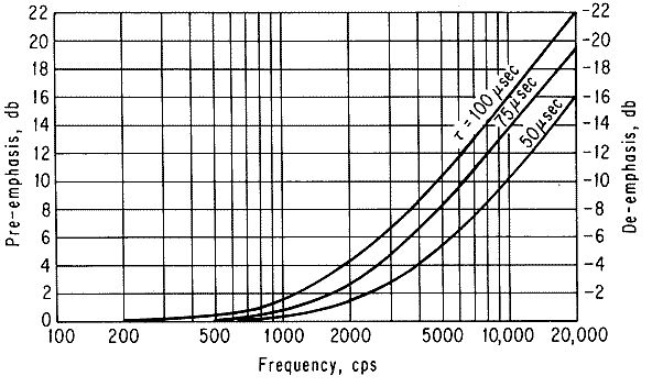
Be mindful of the maximum input level depending on the frequency when 50µs pre-emphasis is active (theoretical +13.6dB boost at 15KHz.).
For example, with DB9506's gain set to minimum and the input level maintained at 1.7Vpp, the output will be 3.9Vpp at 400Hz and 22Vpp at 15KHz, almost ~15dB!
The signal was measured at test point T1, before the LPF. At 22V, the limit is reached beyond this value, the operational amplifiers will clip, causing severe distortion (power supply ±12V).
Therefore, the stereo coder input signal must be preconditioned and processed to avoid preemphasis-induced overmodulation, when the audio program contains high-frequency or sibilance.
At the input of each LPF (left/right), a small header has been provided for adding an external limiter/compressor. Mozart series FM Exciter include a simple safety clipping circuit with two diodes and adjustable bias. This circuit is quite effective, but harsh clipping should be avoided, as it introduces harmonics into the original audio signal, even though the LPF will reject frequencies above 16KHz.
The issue of high-frequency pre-emphasis potentially overmodulating the exciter, especially when trying to achieve modulation as close to 100% as possible with no headroom, can only be properly addressed using a multiband processor, limiter/compressor, de-esser, dynamic pre-emphasis, or other sophisticated circuits. This is why such processors are expensive, as they shape the modulation signature of the station. Nowadays, modulation is typically compressed and dense, sometimes becoming fatiguing for listeners...
In conclusion, a modulation depth close to 100% or ±75 kHz cannot be achieved when the audio program contains a heavy high-frequency spectrum or sibilance ("Sss") found in some singers' vocals.
![]()
![]() Schematic Diagram (PM1000 service manual)
Schematic Diagram (PM1000 service manual)
![]() SI5351A clock oscillator
SI5351A clock oscillator
![]() PCB DB9506 v1.3 (Gerber)
PCB DB9506 v1.3 (Gerber)
![]()
![]() Attiny Firmware SI5351 2.432MHz, I2C 0x60
Attiny Firmware SI5351 2.432MHz, I2C 0x60
![]() Attiny Firmware SI5351 2.432MHz, I2C 0x62
Attiny Firmware SI5351 2.432MHz, I2C 0x62
![]() 19KHz generator section - drift improvment
19KHz generator section - drift improvment
![]()
![]() Mozart Series FM Exciter (schematic)
Mozart Series FM Exciter (schematic)
![]() A four-stage FM broadcast audio peak limiter
A four-stage FM broadcast audio peak limiter
![]() Sibilance Limiter AMN92
Sibilance Limiter AMN92
![]() High Precision Pre-emphasis AMN92
High Precision Pre-emphasis AMN92