LMX2332 27MHz PLL for LNB |
27MHz PLL with LMX2330/1/2 & Attiny25/45/85 (Arduino). The signal is very stable, used to replace the crystal of 10GHz LNB PLL. Reference frequency provided by a 5/10MHz GPSDO or good quality OCXO/TCXO.
I choose a VCXO designed for low phase noise and good stability. Commun AT crystals are possible to use. This PLL can be used for other frequency, Arduino sketch is very flexible. See also LMX2330 prescaler project.
Update 2019: New firmware v2 provided for 25MHz/27MHz VCXO and only 10MHz reference. In this way the PLL can be used for various LNBs.The jumper connected to Attiny pin 2 can select: Open = 27MHz; Close = 25MHz. Of course the VCXO quartz will be installed according necessary frequency.
Excellent results were obtained for Eshail QO-100 reception.
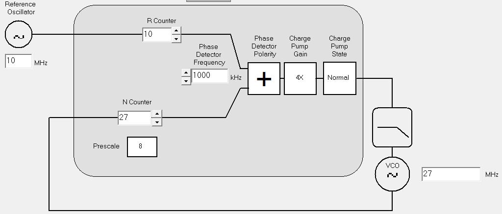
![]() Design requirements:
Design requirements:
- Maximum Phase Detector frequency. Because LMX233x is a N-integer PLL, maximum frequency can be 1MHz. IF PLL section is used for 27MHz (RF PLL disabled).
- VCXO with low Kv gain: 350Hz/V. Control voltage between 0-5V. Low noise power supply, RC filtering. Double varicap diodes, ensure quite good linearity.
- Maximum Charge Pump current: 4mA
- Loop filter bandwith: 365Hz... Phase margin: 54 degree. Filter simulated using ADIsimPLL ADF4217. Free for experiments...
- Low harmonic content. Cauer filter to reject 2nd harmonic. Without filter, 54MHz harmonic is -35...-38dBc.
- Cheap AVR uC, compatible with Arduino environment.
- Possible to select 5 or 10MHz for reference input.
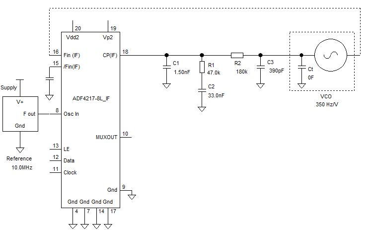
Low Pass Filter - ADIsimPLL simulation:
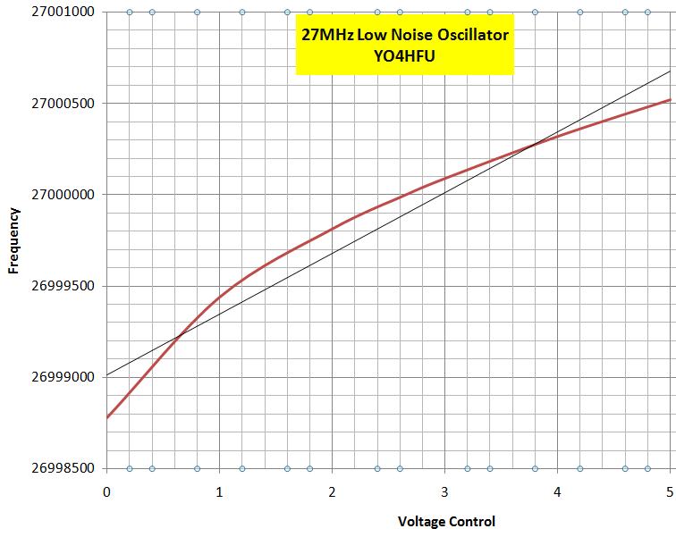
VCO control voltage response (Kv~350Hz/V):
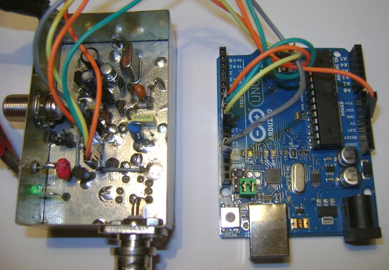
Initial test of PLL, LMX2332 controlled by external Arduino Uno:
![]() Attiny25 Programming
Attiny25 Programming
At the begin the PLL was tested using an ARDUINO UNO board connected to LMX2332 data bus. After that Arduino sketch was adapted for standalone Attiny25/45/85 uC.
Attiny uC is programmed by SPI interface, with AVRISPmkII, USBasp, Arduino Attiny programmer or other model. Don't need to burn any bootloader, Attiny25 has only 2KB flash memory.
Attiny firmware can be programmed by several methods:
Methode #1. Compiled Hex file can be burned using USBasp interface and Xtreme Burner AVR software or other programming interface. Do not forget about USBasp driver installation (Xtreme Burner v 1.4.3 has drivers built into the installer). Connect USBasp with PLL board. PLL board is supplied from programming interface during firmware burning.
For Attiny25/45/85 support, copy and replace "chips & fuselayout" files, typically located in "C:\Program Files\eXtreme Burner - AVR\Data". Attiny default fuse bits no need to be changed, 8MHz internal oscillator is selected from factory. Open Hex file and select Write All. If there are not errors, the Attiny uC is ready to use.
Methode #2. In this case Arduino IDE is used instead of Xtreme Burner. This way is useful when fast modification of sketch is required.
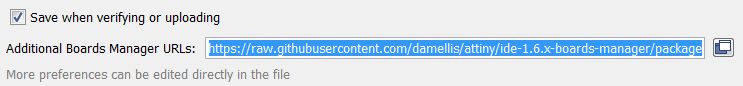
Open Arduino IDE (v1.8 tested).
Go to File/Preferences. Paste following URL: https://raw.githubusercontent.com/damellis/attiny/ide-1.6.x-boards-manager/package_damellis_attiny_index.json and press OK.
Open Tools/Board/Board Manager. Scroll to the bottom of the list; you should see an entry for “ATtiny”. Click on the ATtiny entry. An install button should appear. Click to install button.
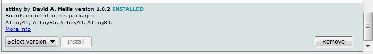
Close Boards Manager. Now you should see an entry for ATtiny in the Tools/ Board menu. Select ATtiny 25/45/85 board, processor: Attint25(used by me), clock internal 8MHz.
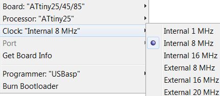
Select USBasp programmer or other model: open Tools/Programmer.
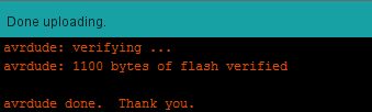
Open LMX2332 PLL sketch. Connect USBasp interface with PLL board. Select Sketch/Upload using programmer. If there are not errors, the uC is ready to use.
Note: if USBasp programmer is not recognized by Arduino IDE, reinstall the driver. See this LINK for more instructions (Plug in USBasp; download Zadig from http://zadig.akeo.ie/; start Zadig; Options>List all devices; Select USBasp from the drop down menu; select libusbK(v3.0.7.0) driver; click Install or Reinstall driver).
![]() Adjustment and tips
Adjustment and tips
Adjust center frequency of VCXO: disconnect 180K resistor located inside of loop filter. Apply 2,5V to varicap control line. Adjust series capacitors (22pF & 3,3pF) until output frequency is very close to 27,000000MHz. Is better to use fixed capacitors. BB329 is a old VHF varicap diode from TV tuners (capacity 35pF/1V; 3pF/30V). Other diodes can be used without any problem if VCXO Kv remain 350Hz/Volt, otherwise loop filter must to be recalculated for optimum performance. Use good quality capacitors for loop filter, MKP polypropylene if it is possible.
Connect spectrum analyzer to oscillator output. The signal must to be very clean, 2nd and 3rd harmonics are below -65 and -70dBc, without any adjustment. Optional, 30MHz Cauer LPF can be fine adjusted for maximum attenuation of 2nd harmonic.
Carrier level is around -9dBm/75ohms. Coaxial cable 50 or 75 ohms can be used to feed the LNB with 27MHz signal. No.2 IF Output of LNB, can be modified to inject 27MHz from LMX PLL, so 75ohms "F" connectors are a good choice.
Before power-up, close the uC switch (jumper) if you use 5MHz reference or open for 10MHz (firmware v1). The reference signal requires stability and accuracy, GPSDO gives best results. Square or sine waves are accepted. 10MHz LPF isn't used, according PLL theory, square signals can avoid jitter noise inside of phase comparator. My spectrum analyzer is too noisy for phase noise measurements, so i don't know what is the reality...In my shack I prefer only sine wave signals in order to avoid any harmonic and spurious response.
LMX lock detector isn't very accurate, but clear indication can be observed for lock condition or reference absence. PLL working good when control line voltage measure 2,5V and LED is on. By touching oscillator parts, the control voltage will be automatically shifted to correct the frequency drift. During power on/off, PLL must to lock the VCXO without any issue.
![]()
![]() LMX2332 27MHz PLL schematic
LMX2332 27MHz PLL schematic
![]() PCB SprintLayout 6 & Pdf
PCB SprintLayout 6 & Pdf
![]()
![]() Arduino Sketch for LMX2330/1/2 & Attiny25/45/85
Arduino Sketch for LMX2330/1/2 & Attiny25/45/85
![]() Hex firmware v1 for VCXO 27MHz and 5/10MHz reference - Attiny25 at 8MHz
Hex firmware v1 for VCXO 27MHz and 5/10MHz reference - Attiny25 at 8MHz
![]() Arduino Sketch & Hex firmware v2 for 25/27MHz VCXO and only 10MHz reference
Arduino Sketch & Hex firmware v2 for 25/27MHz VCXO and only 10MHz reference ![]() * same jumper used as firmware v1
* same jumper used as firmware v1
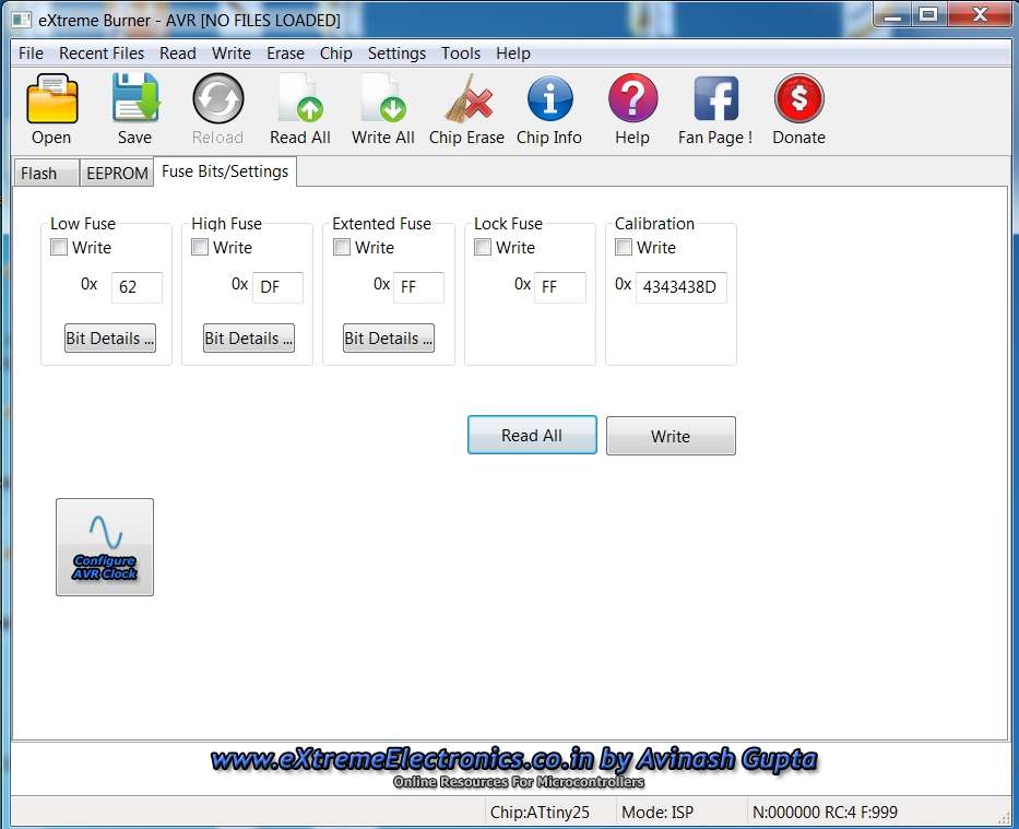
![]() Attiny Fuse Bits (factory default)
Attiny Fuse Bits (factory default)
![]()
![]() Xtreme Burner AVR software v.1.4.3 (link)
Xtreme Burner AVR software v.1.4.3 (link)
![]() Xtreme Burner AVR files for Attiny25/45/85 support
Xtreme Burner AVR files for Attiny25/45/85 support
![]() USBasp connection with PLL board
USBasp connection with PLL board
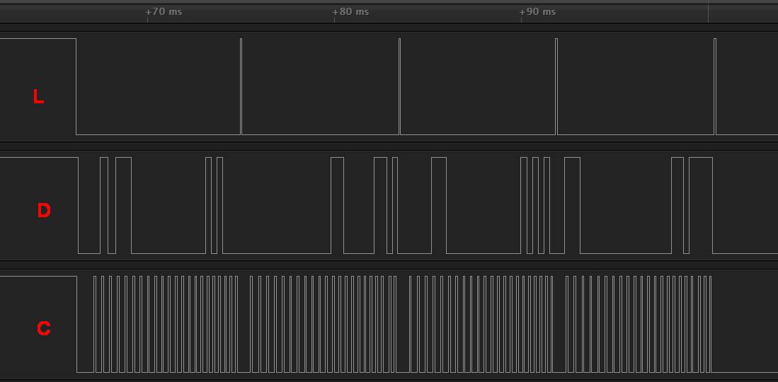
![]() Capture of "3 wire"signal using Saleae Logic Analyzer
Capture of "3 wire"signal using Saleae Logic Analyzer