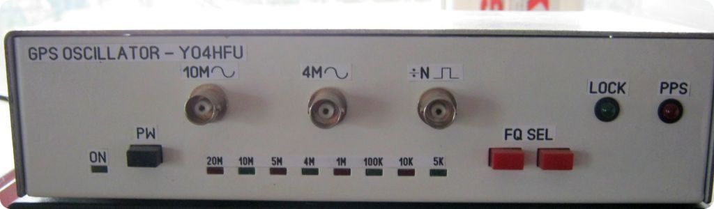
GPS Disciplined Oscillator |
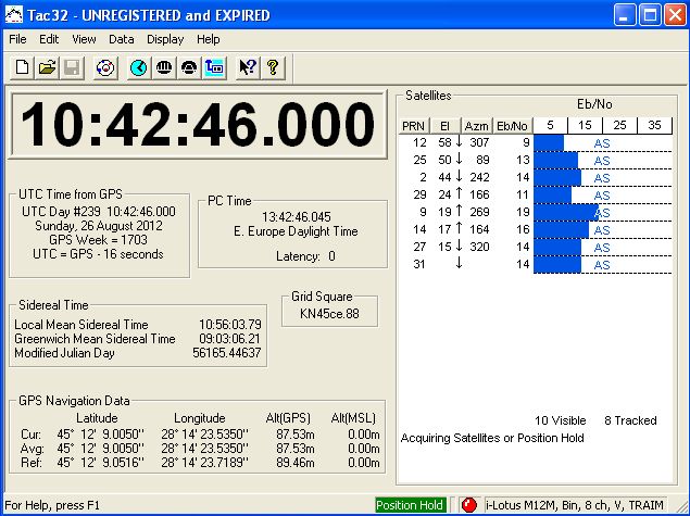
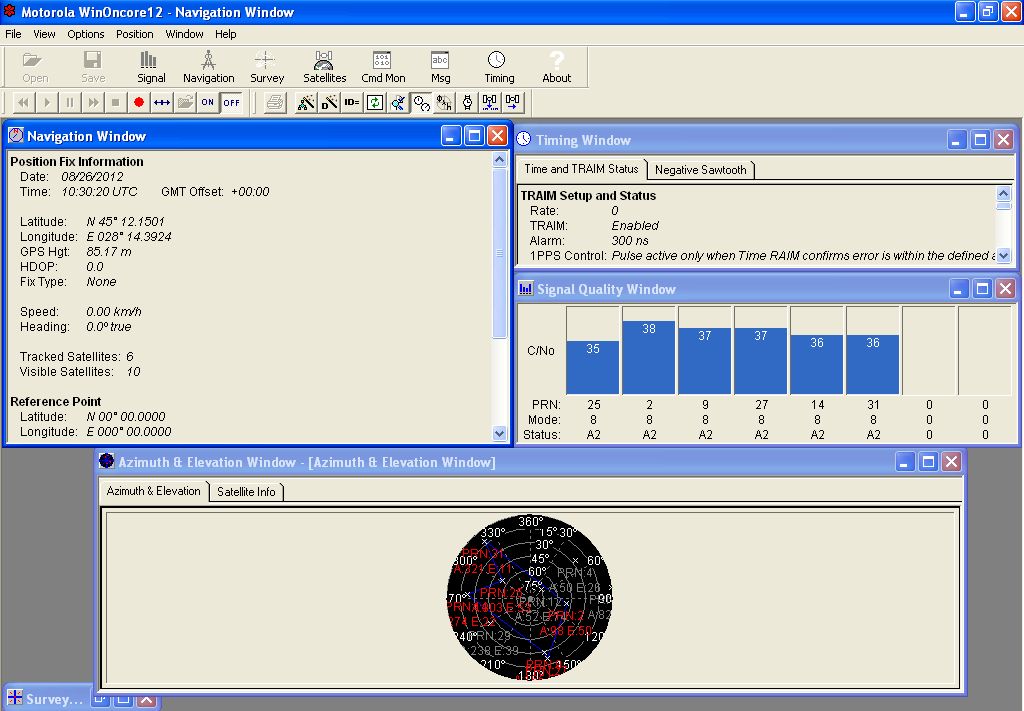
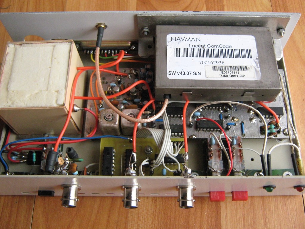
This project use a RX GPS with 10KHz output. In my case the GPS Receiver is a Jupiter TU60-D120 (8 ch NAVMAN, i-Lotus Motorola, Binary Protocol).
The receiver comunicate with PC via RS232. PC software is Tac32 or WinOncore. Print Screens: Tac32, Winoncore.
My project is slightly different from others. The main problem was getting the signal of 4MHz. 10MHz signal had doubled and then divided by 5.
Why is it so important 4MHz? Because it is often used by uC applications such as: counters, signal generators...
The device is able to generate:
10MHz sine 0.5Vpp/50ohms. Second and 3rd harmonics are down to -65...70dB. See 10MHz Oscillogram.
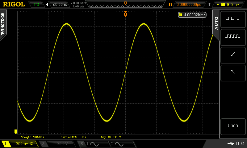
4MHz sine 1Vpp/50ohms.Second harmonic down -30dBc. See 4MHz Oscillogram.
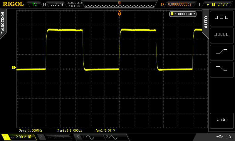
5,10,100KHz, 1,4,5,10,20MHz square wave (TTL/CMOS). See 1MHz Oscillogram.
Antenna is a home made Helical but I recommend industrial GPS antenna and integrated LNA.
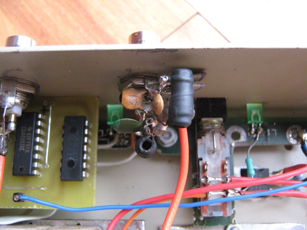
Attention: Helical antenna is a short circuit for DC. Power supply for external antenna must turned OFF. For Jupiter TU60 i removed FB1 inductance. See photo.
Current consumption: 0.8A cold start, then decrease to 0.4A @ 12V.
For best stability performances, the OCXO is located inside of a home made thermal isolation box.
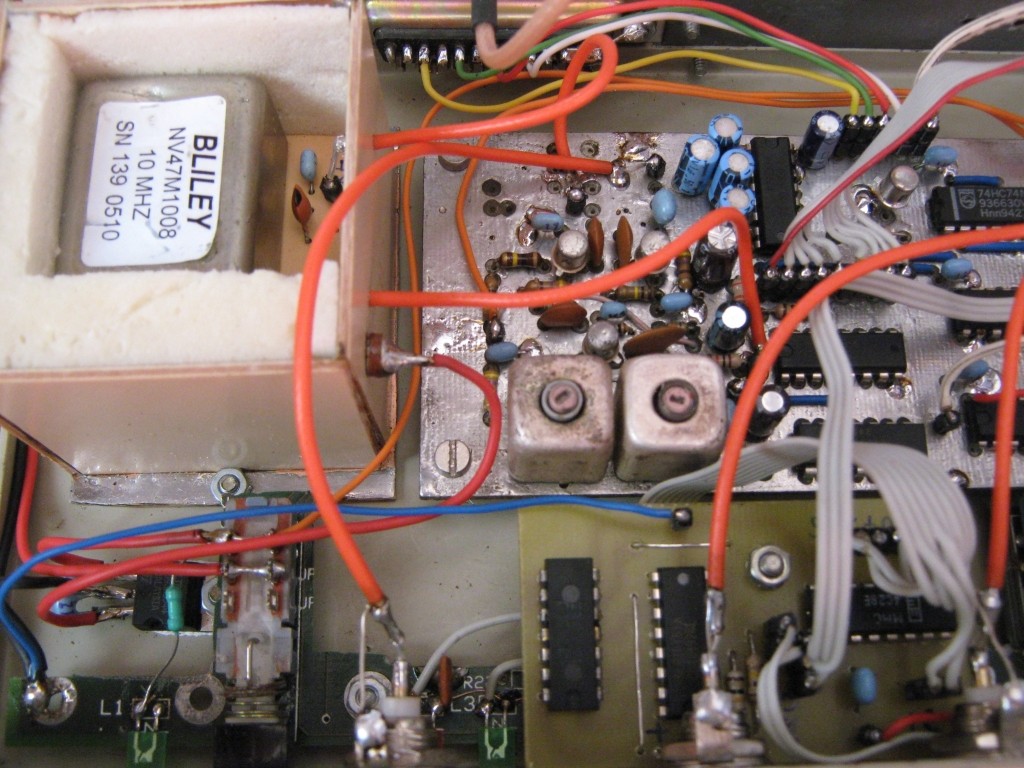
Main 10MHz oscillator can be BLILEY NV47M1008 (Oven Controlled Crystal Oscillator), Kv = 8Hz/V or other similar OCXO. PLL loop filter can be optimized for best result.
GPS Jupiter-T TU60-D125


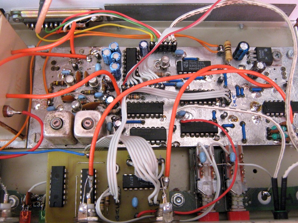
PLL Board and OCXO
LPF Filter 10MHz Output :)
Completed Project
![]()
![]() GPSDO schematic
GPSDO schematic
![]() PCB position
PCB position
![]() PCB bottom
PCB bottom
![]() PCB Sprint Layout
PCB Sprint Layout
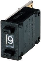
For output frequency selection can use Mechanical BCD Switch or UP/DOWN BCD Counter (40192) + Decimal Decoder (4028).
![]()
![]() Schematic BCD Counter
Schematic BCD Counter
![]() PCB - SprintLayout file
PCB - SprintLayout file
UPDATE 15.03.2023 - Accurate "3D fix Motorola Binary" monitor using Arduino (*old version deleted in order to avoid confusion)
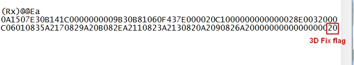
"3D Fix" detection is implemented by reading "@@Ea" receiver status byte.
Initialization of GPS receiver is done by Navman/Motorola Binary protocol. Initalization words are sent one time after 0.25sec from uC power up. RS232 monitoring is not affected.
Tested on Jupiter TU60-125 GPS receiver.
After power up, next commands are sent to GPS Rx:
-
Enable "@@Ea" position/status message;
- Satellite Mask angle 10 degrees;
- Enable 1pps output if TRAIM Alarm is OK (less than 800nsec);
- Position Hold mode (not implemented, but easy to add, instructions inside of sketch)
![]()
![]() Schematic 3D Fix
Schematic 3D Fix
![]() 3D Fix Arduino Sketch v1 2023
3D Fix Arduino Sketch v1 2023
![]() @@Ea message explained
@@Ea message explained
![]() 3D Fix Status reported by @@Ea command
3D Fix Status reported by @@Ea command
![]() Jupiter TU60-125 firmware backup (Flash + EEPROM)
Jupiter TU60-125 firmware backup (Flash + EEPROM)