VHF 2 TONES GENERATOR FOR IMD MEASUREMENTS |
08.2013
Each VCO is controlled with a PLL circuit. I use Philips SA7025 (TRF2050), but any other PLL IC is suitable. LMX series is a good choice, check my web site for more details.
PLL is more complicated than a quartz crystal oscillator, but is cheaper and more flexible.
Output signal is very clean, the second harmonic is attenuated by more than 75dB. Attention to ground connections around the band pass filter. The capacitors (12/56pF) and screens coils must be connected very well to ground at both sides of PCB. BPF has >60dB rejection at 288Mhz. Each oscillator must be screened separately, otherwise interactions occur and signal purity will suffer considerably. I didn't detect spurious signals or harmonics up to -75dBc! Final transistor can be BFG135 or BFG35.
Output power provided by each oscillator is 200mW (+23dBm). Output level can easily balanced using bias adjustement of MOSFET amplifier. It is a good idea to have one bias potentiometer on the front panel.
IMD tester can be configured to generate any frequency between 144-146MHz. Frequency is set by HEX file written inside of uC. Several firmware versions are available for 144.200MHz, 144.201MHz, 144.250MHz, 144.300MHz and 144.400MHz. Use best tones spacing combination according your Spectrum Analyzer capability. If you need other frequency, please visit SA7025 PLL page. I chose a 20MHz TCXO reference oscillator and a frequency of 200KHz for phase detector. You can use a simple crystal oscillator, frequency stability is not critical for IMD measurements.
In this picture oscillators are built on a single board. Later I separate the two oscillators >>FOTO<<.
3 Order products are limited by the Isolation of Hybrid Coupler. I try several versions with 3-7 bifilar turns using several binoculars ferrite for VHF. I haven't noticed significant improvements. An adjustable capacitor (5-15pF) placed at the Output of coupler has helped to increase the isolation between ports A and B.
![]()
![]() Schematic - VCO and Amplifiers<<
Schematic - VCO and Amplifiers<<
![]() Schematic - PLL Section with SA7025<<
Schematic - PLL Section with SA7025<<
![]() Schematic - DJ8ES Combiner<<
Schematic - DJ8ES Combiner<<
![]() DJ8ES Combiner PCB<<
DJ8ES Combiner PCB<<
![]() PCB VCO + PLL (pdf. & SprintLayout)<<
PCB VCO + PLL (pdf. & SprintLayout)<<
![]() Hex Files PIC16F628A (20MHz reference)<<
Hex Files PIC16F628A (20MHz reference)<<
Gallery:
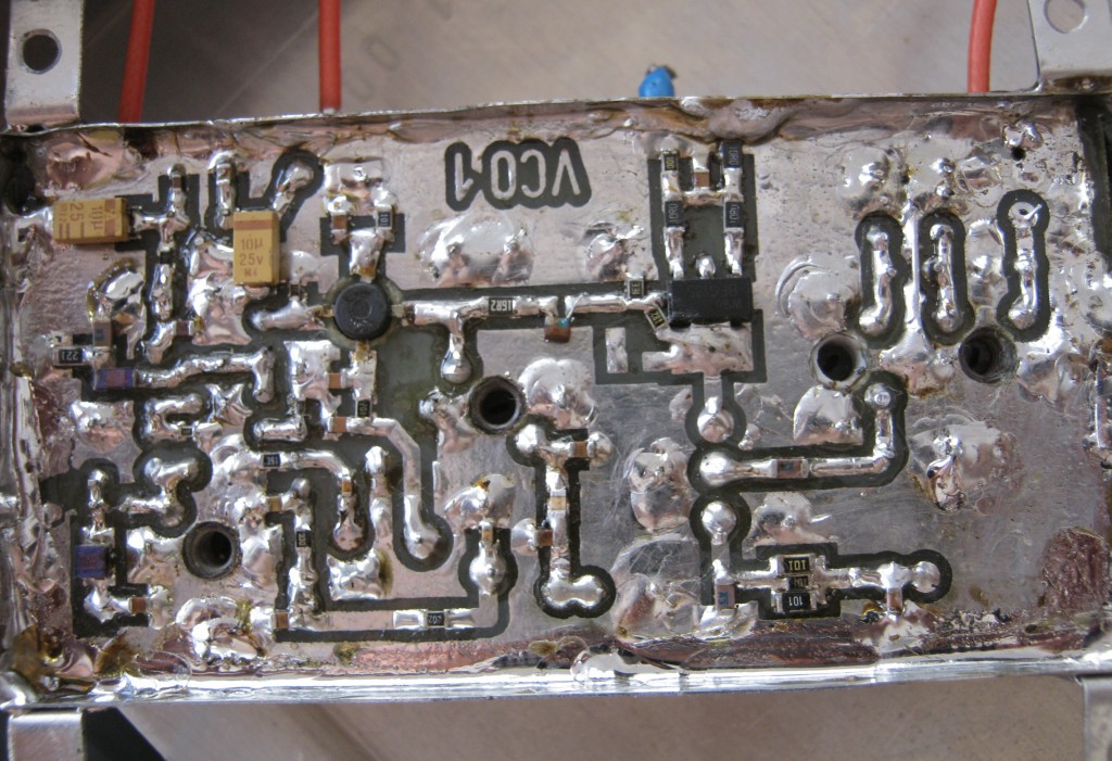
![]() VCO Top
VCO Top
![]() VCO Bottom
VCO Bottom
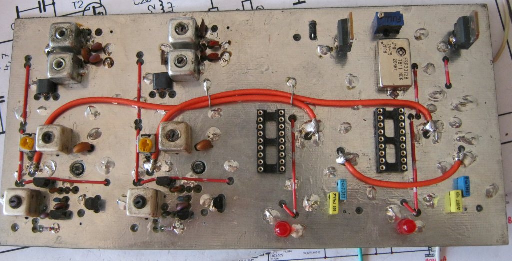
![]() PLL Bottom
PLL Bottom
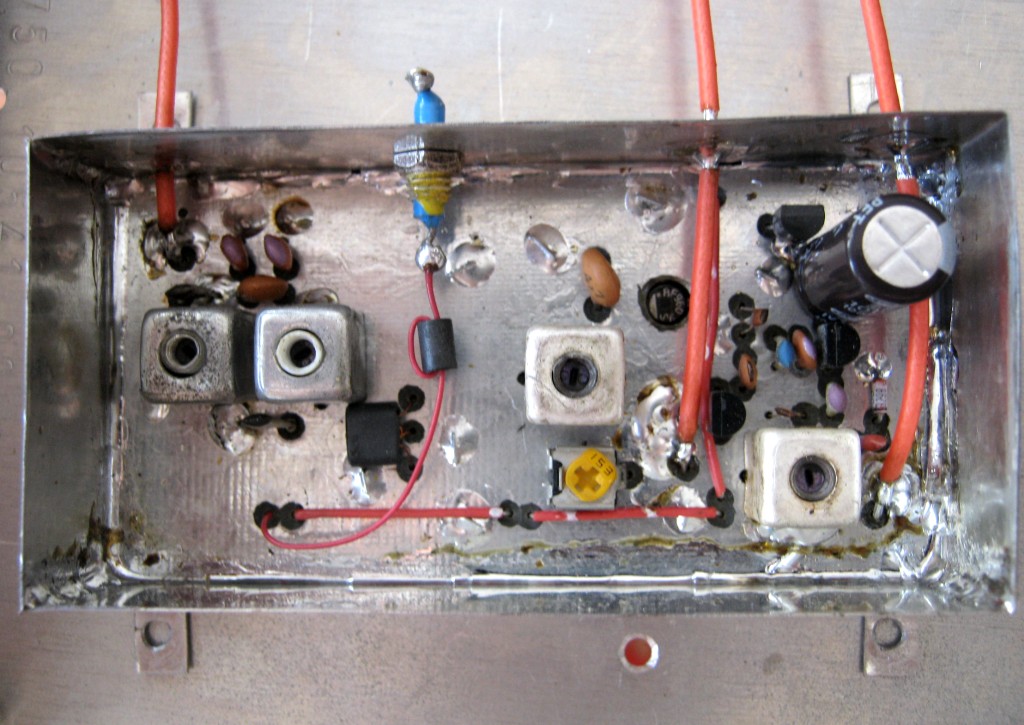
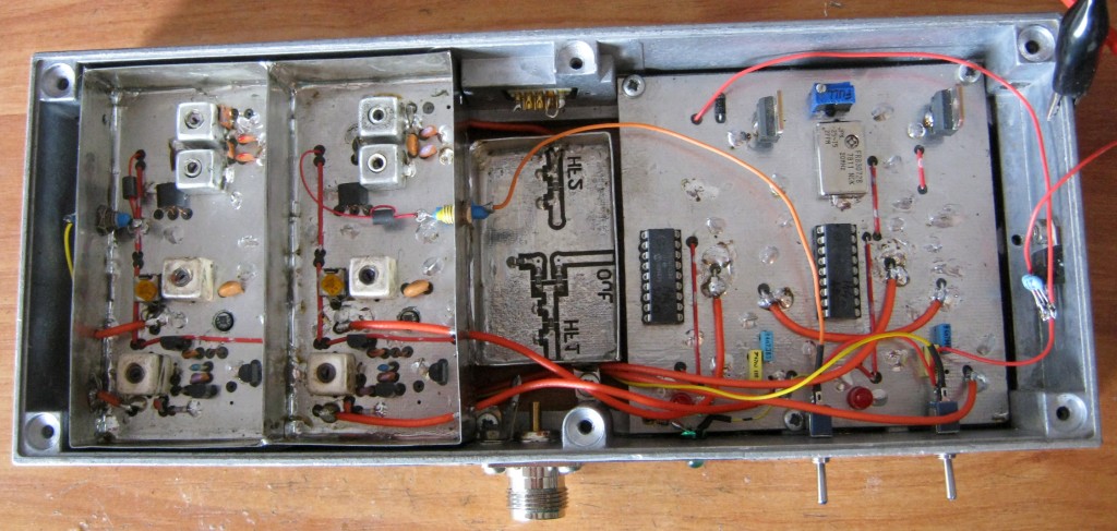
![]() First enclosure - Poor Separation between VCO 1 and VCO 2. Do not use small distance between VCO 1 & 2 !
First enclosure - Poor Separation between VCO 1 and VCO 2. Do not use small distance between VCO 1 & 2 !
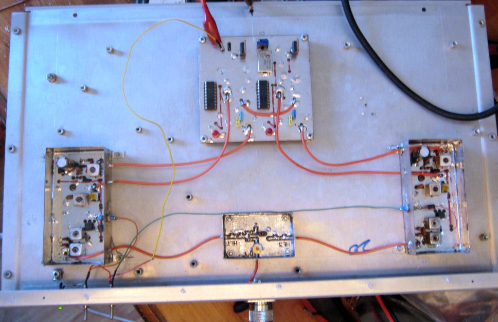
![]() Second enclosure - Now Separation is very good
Second enclosure - Now Separation is very good
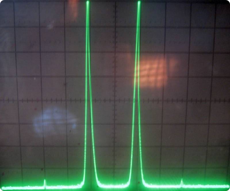
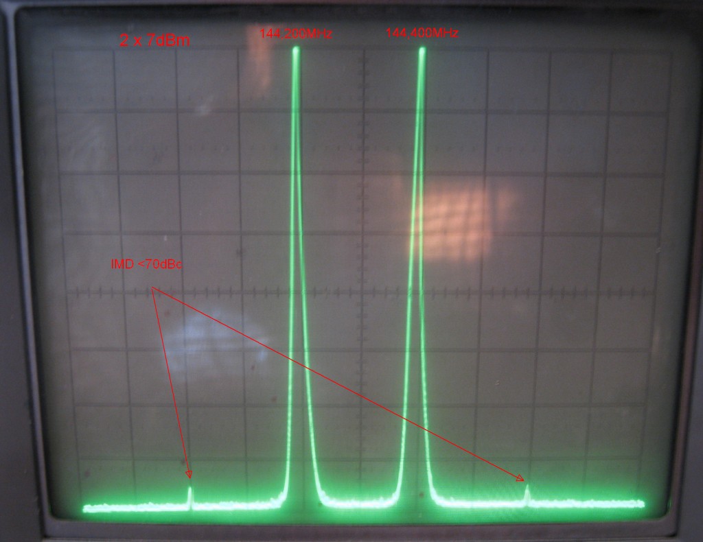
![]() Output Signal - 3 Order Products better than 70dBc. Two tones 2 x 5mW (+7dBm). Average Output Power is 10mW (+10dBm). PEP Power is 20mW (+13dBm).
Output Signal - 3 Order Products better than 70dBc. Two tones 2 x 5mW (+7dBm). Average Output Power is 10mW (+10dBm). PEP Power is 20mW (+13dBm).
About IMD:
![]() VHF 2 Tone Generator - VHF Communications 4/2002
VHF 2 Tone Generator - VHF Communications 4/2002
![]() HF 2 Tone Exciter - Radiotechika 1/2002
HF 2 Tone Exciter - Radiotechika 1/2002
![]() Intermodulation Properties of Switching Diodes - VHF Communications 1/1994
Intermodulation Properties of Switching Diodes - VHF Communications 1/1994
![]() Hybrid Combiners - ARRL HANDBOOK
Hybrid Combiners - ARRL HANDBOOK
![]() How to Calculate Power for Multi Tones
How to Calculate Power for Multi Tones
![]() IMD Homebrew- RGSB january 2009
IMD Homebrew- RGSB january 2009
![]() High Dinamic Range receiver input stages - HamRadio oct.1975
High Dinamic Range receiver input stages - HamRadio oct.1975
![]() A Precision Two-Tone RF Generator for IMD Measurements - QEX April 1995
A Precision Two-Tone RF Generator for IMD Measurements - QEX April 1995
![]() Reducing IMD in High-Level Mixers
Reducing IMD in High-Level Mixers