DIGITAL MODES
Amateur Television (ATV)
Amateur High Definition Television by Jim Andrews, KH6HTV (pdf slides)
ATV Handbook by Jim Andrews, KH6HTV
I’ve collected as many of Jim’s newsletters as possible for your reading enjoyment. Will post shortly.
MY ACTIVITIES: I was always interested in ATV, even from an non-licensed amateur for model rocketry. I discovered PC Electronics
and bought a few items after I got my license. My interest faded due to the lack of other ATV operators in the area. But
C4FM System Fusion - Yaesu
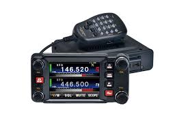
FTM-400DR
Quick Guide
Manual
Wires-X via DG-ID
Wires-X Node Manual
MY ACTIVITIES: I needed an alternate to DMR, so I chose Yaesu’s System Fusion. Also known as Compatible 4-level Frequency
Modulation, CF4M is a digital voice and data communication mode used primarily in amateur radio. It uses digital tones to transmit
crisp audio, GPS coordinates, and call signs across VHF/UHF frequencies. I love the color display and ease of use, especially for APRS.
I own two UHF analog/fusion repeaters.
DMR
Connect Systems Incorporated
CS800D PLUS
Software/Firmware
DMR (Digital Mobile Radio)
DMARC
BrandMeister Network: Dashboard
MY ACTIVITIES: My first DMR radio was a CSI handheld CS700 for UHF. Due to the mountainous terrain, I upgraded to Vertex VXD-
7200 mobile followed by a CS800 all of which are a pain in the next to program. The CS800D boasts ease of programming and more
digital mode. I picked one up and time will tell. Unfortunately, the only DMR repeater I can hit from my home QTH is down.
FT2/FT4/FT8
FT2: Features an ultra-fast 3.8-second transmit/receive cycle, allowing a complete QSO (contact) in about 11 seconds. It is optimized
for contests and pile-ups where signals are strong. However, it is significantly less sensitive than FT8 and requires a modified,
separate software program called Decodium rather than the official WSJT-X.
FT4: Has a 7.5-second transmit/receive cycle. It was developed by the WSJT-X creators specifically for contesting. It offers a good
balance of speed and sensitivity without needing extreme automation.
FT8: The gold standard for weak-signal communication. It uses a 15-second transmit/receive cycle, which allows it to decode signals
deep into the noise.
FT8 Operating Guide - Weak Signal HF DXing for technophiles - by Gary Hinsen ZL2IFB
MY ACTIVITIES: Running FT4/FT8 on a laptop connected to a Kenwood TS-480HX via a XGGComms Digimode-4-Kenwood from the
car or picnic table made POTA so much fun! Using an Alpha antenna really helped on weak contacts, with my best FT8 contact to
Indonesia.
FX.25
FX.25 is a protocol extension to the AX.25 Link Layer Protocol. FX.25 provides a forward error correction (FEC) capability while
maintaining legacy compatibility with non-FEC equipment. FX.25 was created by the Stensat Group in 2005, and was presented as a
technical paper at the 2006 TAPR Digital Communications Conference in Tucson.
Overview
FX.25 is intended to complement the AX.25 protocol, not replace it. It provides an encapsulation mechanism that does not alter the
AX.25 data or functionalities. An error correction capability is introduced at the bottom of Layer 2 in the OSI model.
The AX.25 Link Layer Protocol is extensively used in amateur radio communications. The packets are validated by a 16-bit CRC, and
are discarded if one or more errors are detected. In many cases, such as space-to-earth telemetry, the packets are broadcast
unidirectionally. No back-channel may be available to request retransmission of errored elements. Consequently, AX.25 links are
inherently intolerant of errors.
The FX.25 protocol extension provides an error correction "wrapper" around the AX.25 packet, allowing for removal of errors at the
receiving end. Data fields have been carefully chosen to allow reception of the AX.25 packet data within an FX.25 frame by a non-
FEC decoder. (https://en.wikipedia.org/wiki/FX.25_Forward_Error_Correction)
MY ACTIVITIES: Having a strong attraction to hardware TNCs, I decided to pick up a Kantronics KPC-XE USB 1MB TNC for two main
reasons: 1MB mailbox and their latest digital mode addition: FX.25 which is great for low signal data.
IL2P
IL2P (Improved Layer 2 Protocol) is a data link layer protocol originally derived from layer 2 of the X.25 protocol suite and designed
for use by amateur radio operators. It is used exclusively on amateur packet radio networks.
IL2P establishes link layer connections, transferring data encapsulated in frames between nodes, and detecting errors introduced by
the communications channel.
The Improved Layer 2 Protocol (IL2P) was created by Nino Carrillo, KK4HEJ, based on AX.25 version 2.0 and implements
Reed–Solomon forward error correction for greater accuracy and throughput than either AX.25 or FX.25. Specifically, in order to
achieve greater stability on link speeds higher than 1200 baud.
IL2P can be used with a variety of modulation methods including AFSK and GFSK. The direwolf software TNC contains the first open
source implementation of the protocol. (https://en.wikipedia.org/wiki/Improved_Layer_2_Protocol)
MY ACTIVITIES: I’m not fan of IL2P. It’s not compatible with AX.25 packet systems. Therefore, I’m leaving this one alone for the
TARPN group.
PACTOR
PACTOR can be viewed as a combination of two earlier digital modes, packet radio and AMateur Teleprinting Over Radio (AMTOR).
PACTOR provides improved throughput because its transmission speed adapts to the quality of the link and it uses Huffman
compressed characters. PACTOR operates over half-duplex links and uses an Automatic Repeat reQuest (ARQ) protocol,
acknowledging each individual data packet with a short Control Signal (CS). Some PACTOR implementations provide a Memory-ARQ
feature to determine and store the relative strength of each received bit. Copies of corrupted frames stored this way are correlated
with frames received later, to provide a coding gain for improved error correction. (https://www.arrl.org/pactor)
MY ACTIVITIES: Still exploring PACTOR 1 through 4.
POCSAG Paging
While commercial paging has virtually disappeared, the amateur radio community has embraced this technology.
Technical Data/Theory of Operation
Digital Amateur POCSAG Paging
Ham Radio Paging: Putting "POCSAG" on Packet W0XI
POCSAG Paging Protocol - Raveon
Hardware
Alphapoc German manufacturer of pagers that cover the amateur frequencies.
Kantronics has the 9612+ (out of production) and the newer 9612XE can encode/decode POCSAG.
Wireless Devices Inc (Taiwan) These guys have tons of fun POSCAG toys! Their hardware including their pagers cover 2 meter and
440 amateur radio frequencies!
NP-14 Series fully-programmable, single-board, POCSAG encoder with Hi power synthesized transmitter for the on-site paging
system applications.
POCSAG Encoder/Transmitter Module for IoT Application. Great item that will intercept your page and send it to your phone!
Salcom 12-62-0000 POCSAG Paging Transmitter
STI Engineering in Australia. WOW! Full VHF Band POCSAG Paging Trasmitters with and without Built-in Encoder that covers the 2
meter amateur radio band. The shame of it is they are grossly overpriced!!
Software
PE
PE v3.10a by Clive Cooper, G8UKN and Pete Baston, GW0PJA is a DOS paging encoder for the PC. This is the software. I have
the article on the interface by Robert B. Whitaker, but alas, I don’t have the schematics anymore. Check back often. This is on my
list. In the mean time check out PDW below.
PE-300
PDW
Since 2003, Peter Hunt has made PDW the main (free!) Program to receive POCSAG and FLEX. PDW has users worldwide, from
radio hobbyists to professional users. Peter has stopped developing the program after 10 years: he thinks it is 'finished'. Peter,
thank you for all your efforts! PDW is now Open Source.
The official site is HERE. These files are achieved locally and act as a mirror if/when the site goes down.
PDW and RS-232 Port.doc
PDW FSK to RS232 Schematics
PDW2.14-full
PDW2.2-full
PDW3.10-full
PDW3.12-full
PDW3.2b01
MY ACTIVITIES: Currently, my Kantronics Node Stack incorporates a POCSAG Paing Server. Works nicely! Working on a paper on this.
Robust Packet
Robust PACKET, also known as HF-APRS, RPR, Winlink RMS, APRSlink, RPR-HF-APRS, and SCS Robust Packet, is an OFDM version of
the amateur mode PACKET optimized for shortwave use. This mode was developed by Spezielle Communications Systeme GmbH &
Co. KG (SCS), who developed the PACTOR protocol.
Robust PACKET uses 500 Hz of bandwidth with 60 Hz spacing between carriers, and uses OFDM with 8 DBPSK or DQPSK carriers. On
200 bps mode, it uses BPSK. For 600 bps mode, DQPSK is used. For both modes, each subcarrier runs at a constant rate of 50 Bd.
Like PACKET, Robust PACKET uses the AX-25 frame protocol for transmitting data. Compared to PACKET, Robust PACKET has better
resistance against multipath propagation and fading. In addition, Robust PACKET takes less total bandwidth, with sidebands only
extending out to 500 Hz, where with PACKET, the sidebands produced from the 300 Bd FSK extend as far as 730 Hz.
(https://www.sigidwiki.com/wiki/Robust_PACKET)
MY ACTIVITIES: Purchased a couple of modems. Haven’t had time to implement this mode yet.
RTTY
RTTY (Radio TeleTYpe) is one of the oldest digital communication modes, dating back to World War II. Originally used by the military
to send text messages via large mechanical teleprinters, it is now primarily used by amateur (ham) radio operators to send typed
text over the airwaves
Radioteletype (RTTY)[a] is a telecommunications system consisting originally of two or more electromechanical teleprinters in
different locations connected by radio rather than a wired link. Radioteletype evolved from earlier landline teleprinter operations that
began in the mid-1800s.[1] The US Navy Department successfully tested printing telegraphy between an airplane and ground radio
station in 1922. Later that year, the Radio Corporation of America (RCA) successfully tested printing telegraphy via their Chatham,
Massachusetts, radio station to the RMS Majestic. Commercial RTTY systems were in active service between San Francisco and
Honolulu as early as April 1932 and between San Francisco and New York City by 1934. The US military used radioteletype in the
1930s and expanded this usage during World War II. From the 1980s, teleprinters were replaced by personal computers (PCs)
running software to emulate teleprinters. (https://en.wikipedia.org/wiki/Radioteletype)
RTTY (Also known as Baudot or ITA2) uses the Baudot 5-bit alphabet with FSK to send text messages over the shortwave. This mode
is gradually dying out in favor of more robust modes like PSK31 in the amateur service. Uses the ITA-2 alphabet (Commonly known
as Baudot, derived from the Murray code). Apart from occasional ham use, the only other known user is the Deutscher Wetterdienst
(German Meteorological Service).
Among amateur radio, the most common default mode of RTTY is 170 Hz with 45.45Bd. (https://www.sigidwiki.com/wiki/RTTY)
Great articles I found on RTTY:
Getting Started on RTTY
Radio Teletype or RTTY by the Wireless Institute of Australia
RTTY over Internet: test your sound card by receiving RTTY over the internet!
MY ACTIVITIES: If it wasn’t for RTTY, I never would have gotten into digital modes. As a SWL, I would decode Associated Press
transmissions using a PK-232. My bucket list is to set up a RTTY MSO someday.
SSTV
Slow-scan television (SSTV) is a method for picture transmission used by amateur radio operators to transmit and receive images. A
technical term for SSTV is narrowband television. The most popular modes of SSTV are Robot, Scottie, and Martin.
Commercial analog television signals require 6 to 8 MHz of bandwidth, because it transmits 25 or 30 picture frames per second (in
the NTSC, PAL or SECAM color systems), but SSTV usually only takes up a maximum of 3 kHz of bandwidth. It is a much slower
method of still picture transmission, usually taking from about eight seconds to a couple of minutes, depending on the mode used, to
transmit one image frame.
SSTV uses analog frequency modulation, in which every different value of brightness in the image gets a different audio frequency. In
other words, the signal frequency shifts up to create brighter pixels and shifts down to create darker pixels. Color is achieved by
sending the brightness of each color component (usually red, green and blue) separately.
Sync is 1100 to 1300 Hz; channel information is 1500 to 2300 Hz. (https://www.sigidwiki.com/wiki/SSTV)
MY ACTIVITIES: I have had brief, yet enjoyable experiences operating SSTV on 20 meters (14.230 Mhz USB) using Ham RAdio
Deluxe several years ago. At the time, my transmitted pictures were slightly skewed due to frequency deviations in my clock. I’d like
to get back into SSTV again. The software is the only thing holding me up.
Report any broken links to ww2bsa@arrl.net
AMATEUR RADIO STATIONWW2BSA


DIGITAL
MODES

Amateur Television (ATV)
Amateur High Definition Television by Jim
Andrews, KH6HTV (pdf slides)
ATV Handbook by Jim Andrews, KH6HTV
I’ve collected as many of Jim’s newsletters
as possible for your reading enjoyment. Will
post shortly.
MY ACTIVITIES: I was always interested in
ATV, even from an non-licensed amateur for
model rocketry. I discovered PC Electronics
and bought a few items after I got my
license. My interest faded due to the lack of
other ATV operators in the area. But
C4FM System Fusion - Yaesu
FTM-400DR
Quick Guide
Manual
Wires-
X via DG-ID
Wires-X Node Manual
MY ACTIVITIES: I needed an alternate to
DMR, so I chose Yaesu’s System Fusion. Also
known as Compatible 4-level Frequency
Modulation, CF4M is a digital voice and data
communication mode used primarily in
amateur radio. It uses digital tones to
transmit crisp audio, GPS coordinates, and
call signs across VHF/UHF frequencies. I love
the color display and ease of use, especially
for APRS. I own two UHF analog/fusion
repeaters.
DMR
Connect Systems Incorporated
CS800D PLUS
Software/Firmware
DMR (Digital Mobile Radio)
DMARC
BrandMeister Network: Dashboard
MY ACTIVITIES: My first DMR radio was a
CSI handheld CS700 for UHF. Due to the
mountainous terrain, I upgraded to Vertex
VXD-7200 mobile followed by a CS800 all of
which are a pain in the next to program. The
CS800D boasts ease of programming and
more digital mode. I picked one up and time
will tell. Unfortunately, the only DMR
repeater I can hit from my home QTH is
down.
FT2/FT4/FT8
FT2: Features an ultra-fast 3.8-second
transmit/receive cycle, allowing a complete
QSO (contact) in about 11 seconds. It is
optimized for contests and pile-ups where
signals are strong. However, it is
significantly less sensitive than FT8 and
requires a modified, separate software
program called Decodium rather than the
official WSJT-X.
FT4: Has a 7.5-second transmit/receive
cycle. It was developed by the WSJT-X
creators specifically for contesting. It offers
a good balance of speed and sensitivity
without needing extreme automation.
FT8: The gold standard for weak-signal
communication. It uses a 15-second
transmit/receive cycle, which allows it to
decode signals deep into the noise.
FT8 Operating Guide - Weak Signal HF
DXing for technophiles - by Gary Hinsen
ZL2IFB
MY ACTIVITIES: Running FT4/FT8 on a
laptop connected to a Kenwood TS-480HX
via a XGGComms Digimode-4-Kenwood from
the car or picnic table made POTA so much
fun! Using an Alpha antenna really helped
on weak contacts, with my best FT8 contact
to Indonesia.
FX.25
FX.25 is a protocol extension to the AX.25
Link Layer Protocol. FX.25 provides a
forward error correction (FEC) capability
while maintaining legacy compatibility with
non-FEC equipment. FX.25 was created by
the Stensat Group in 2005, and was
presented as a technical paper at the 2006
TAPR Digital Communications Conference in
Tucson.
Overview
FX.25 is intended to complement the AX.25
protocol, not replace it. It provides an
encapsulation mechanism that does not alter
the AX.25 data or functionalities. An error
correction capability is introduced at the
bottom of Layer 2 in the OSI model.
The AX.25 Link Layer Protocol is extensively
used in amateur radio communications. The
packets are validated by a 16-bit CRC, and
are discarded if one or more errors are
detected. In many cases, such as space-to-
earth telemetry, the packets are broadcast
unidirectionally. No back-channel may be
available to request retransmission of
errored elements. Consequently, AX.25 links
are inherently intolerant of errors.
The FX.25 protocol extension provides an
error correction "wrapper" around the AX.25
packet, allowing for removal of errors at the
receiving end. Data fields have been
carefully chosen to allow reception of the
AX.25 packet data within an FX.25 frame by
a non-FEC decoder.
(https://en.wikipedia.org/wiki/FX.25_Forwar
d_Error_Correction)
MY ACTIVITIES: Having a strong attraction
to hardware TNCs, I decided to pick up a
Kantronics KPC-XE USB 1MB TNC for two
main reasons: 1MB mailbox and their latest
digital mode addition: FX.25 which is great
for low signal data.
IL2P
IL2P (Improved Layer 2 Protocol) is a data
link layer protocol originally derived from
layer 2 of the X.25 protocol suite and
designed for use by amateur radio
operators. It is used exclusively on amateur
packet radio networks.
IL2P establishes link layer connections,
transferring data encapsulated in frames
between nodes, and detecting errors
introduced by the communications channel.
The Improved Layer 2 Protocol (IL2P) was
created by Nino Carrillo, KK4HEJ, based on
AX.25 version 2.0 and implements
Reed–Solomon forward error correction for
greater accuracy and throughput than either
AX.25 or FX.25. Specifically, in order to
achieve greater stability on link speeds
higher than 1200 baud.
IL2P can be used with a variety of
modulation methods including AFSK and
GFSK. The direwolf software TNC contains
the first open source implementation of the
protocol.
(https://en.wikipedia.org/wiki/Improved_La
yer_2_Protocol)
MY ACTIVITIES: I’m not fan of IL2P. It’s not
compatible with AX.25 packet systems.
Therefore, I’m leaving this one alone for the
TARPN group.
PACTOR
PACTOR can be viewed as a combination of
two earlier digital modes, packet radio and
AMateur Teleprinting Over Radio (AMTOR).
PACTOR provides improved throughput
because its transmission speed adapts to
the quality of the link and it uses Huffman
compressed characters. PACTOR operates
over half-duplex links and uses an Automatic
Repeat reQuest (ARQ) protocol,
acknowledging each individual data packet
with a short Control Signal (CS). Some
PACTOR implementations provide a Memory-
ARQ feature to determine and store the
relative strength of each received bit. Copies
of corrupted frames stored this way are
correlated with frames received later, to
provide a coding gain for improved error
correction. (https://www.arrl.org/pactor)
MY ACTIVITIES: Still exploring PACTOR 1
through 4.
POCSAG Paging
While commercial paging has virtually
disappeared, the amateur radio community
has embraced this technology.
Technical Data/Theory of Operation
Digital Amateur POCSAG Paging
Ham Radio Paging: Putting "POCSAG" on
Packet W0XI
POCSAG Paging Protocol - Raveon
Hardware
Alphapoc German manufacturer of pagers
that cover the amateur frequencies.
Kantronics has the 9612+ (out of
production) and the newer 9612XE can
encode/decode POCSAG.
Wireless Devices Inc (Taiwan) These guys
have tons of fun POSCAG toys! Their
hardware including their pagers cover 2
meter and 440 amateur radio frequencies!
NP-14 Series fully-programmable,
single-board, POCSAG encoder with Hi
power synthesized transmitter for the on-
site paging system applications.
POCSAG Encoder/Transmitter Module for
IoT Application. Great item that will
intercept your page and send it to your
phone!
Salcom 12-62-0000 POCSAG Paging
Transmitter
STI Engineering in Australia. WOW! Full
VHF Band POCSAG Paging Trasmitters with
and without Built-in Encoder that covers
the 2 meter amateur radio band. The
shame of it is they are grossly overpriced!!
Software
PE
PE v3.10a by Clive Cooper, G8UKN and
Pete Baston, GW0PJA is a DOS paging
encoder for the PC. This is the software.
I have the article on the interface by
Robert B. Whitaker, but alas, I don’t
have the schematics anymore. Check
back often. This is on my list. In the
mean time check out PDW below.
PE-300
PDW
Since 2003, Peter Hunt has made PDW
the main (free!) Program to receive
POCSAG and FLEX. PDW has users
worldwide, from radio hobbyists to
professional users. Peter has stopped
developing the program after 10 years:
he thinks it is 'finished'. Peter, thank you
for all your efforts! PDW is now Open
Source.
The official site is HERE. These files are
achieved locally and act as a mirror
if/when the site goes down.
PDW and RS-232 Port.doc
PDW FSK to
RS232 Schematics
PDW2.14-full
PDW2.2-full
PDW3.10-
full
PDW3.12-full
PDW3.2b01
MY ACTIVITIES: Currently, my Kantronics
Node Stack incorporates a POCSAG Paing
Server. Works nicely! Working on a paper on
this.
Robust Packet
Robust PACKET, also known as HF-APRS,
RPR, Winlink RMS, APRSlink, RPR-HF-APRS,
and SCS Robust Packet, is an OFDM version
of the amateur mode PACKET optimized for
shortwave use. This mode was developed by
Spezielle Communications Systeme GmbH &
Co. KG (SCS), who developed the PACTOR
protocol.
Robust PACKET uses 500 Hz of bandwidth
with 60 Hz spacing between carriers, and
uses OFDM with 8 DBPSK or DQPSK carriers.
On 200 bps mode, it uses BPSK. For 600 bps
mode, DQPSK is used. For both modes, each
subcarrier runs at a constant rate of 50 Bd.
Like PACKET, Robust PACKET uses the AX-25
frame protocol for transmitting data.
Compared to PACKET, Robust PACKET has
better resistance against multipath
propagation and fading. In addition, Robust
PACKET takes less total bandwidth, with
sidebands only extending out to 500 Hz,
where with PACKET, the sidebands produced
from the 300 Bd FSK extend as far as 730
Hz.
(https://www.sigidwiki.com/wiki/Robust_PA
CKET)
MY ACTIVITIES: Purchased a couple of
modems. Haven’t had time to implement
this mode yet.
RTTY
RTTY (Radio TeleTYpe) is one of the oldest
digital communication modes, dating back to
World War II. Originally used by the military
to send text messages via large mechanical
teleprinters, it is now primarily used by
amateur (ham) radio operators to send
typed text over the airwaves
Radioteletype (RTTY)[a] is a
telecommunications system consisting
originally of two or more electromechanical
teleprinters in different locations connected
by radio rather than a wired link.
Radioteletype evolved from earlier landline
teleprinter operations that began in the mid-
1800s.[1] The US Navy Department
successfully tested printing telegraphy
between an airplane and ground radio
station in 1922. Later that year, the Radio
Corporation of America (RCA) successfully
tested printing telegraphy via their
Chatham, Massachusetts, radio station to
the RMS Majestic. Commercial RTTY systems
were in active service between San
Francisco and Honolulu as early as April
1932 and between San Francisco and New
York City by 1934. The US military used
radioteletype in the 1930s and expanded
this usage during World War II. From the
1980s, teleprinters were replaced by
personal computers (PCs) running software
to emulate teleprinters.
(https://en.wikipedia.org/wiki/Radioteletype
)
RTTY (Also known as Baudot or ITA2) uses
the Baudot 5-bit alphabet with FSK to send
text messages over the shortwave. This
mode is gradually dying out in favor of more
robust modes like PSK31 in the amateur
service. Uses the ITA-2 alphabet (Commonly
known as Baudot, derived from the Murray
code). Apart from occasional ham use, the
only other known user is the Deutscher
Wetterdienst (German Meteorological
Service).
Among amateur radio, the most common
default mode of RTTY is 170 Hz with
45.45Bd.
(https://www.sigidwiki.com/wiki/RTTY)
Great articles I found on RTTY:
Getting Started on RTTY
Radio Teletype or RTTY by the Wireless
Institute of Australia
RTTY over Internet: test your sound card by
receiving RTTY over the internet!
MY ACTIVITIES: If it wasn’t for RTTY, I never
would have gotten into digital modes. As a
SWL, I would decode Associated Press
transmissions using a PK-232. My bucket list
is to set up a RTTY MSO someday.
SSTV
Slow-scan television (SSTV) is a method for
picture transmission used by amateur radio
operators to transmit and receive images. A
technical term for SSTV is narrowband
television. The most popular modes of SSTV
are Robot, Scottie, and Martin.
Commercial analog television signals require
6 to 8 MHz of bandwidth, because it
transmits 25 or 30 picture frames per
second (in the NTSC, PAL or SECAM color
systems), but SSTV usually only takes up a
maximum of 3 kHz of bandwidth. It is a
much slower method of still picture
transmission, usually taking from about
eight seconds to a couple of minutes,
depending on the mode used, to transmit
one image frame.
SSTV uses analog frequency modulation, in
which every different value of brightness in
the image gets a different audio frequency.
In other words, the signal frequency shifts
up to create brighter pixels and shifts down
to create darker pixels. Color is achieved by
sending the brightness of each color
component (usually red, green and blue)
separately.
Sync is 1100 to 1300 Hz; channel
information is 1500 to 2300 Hz.
(https://www.sigidwiki.com/wiki/SSTV)
MY ACTIVITIES: I have had brief, yet
enjoyable experiences operating SSTV on 20
meters (14.230 Mhz USB) using Ham RAdio
Deluxe several years ago. At the time, my
transmitted pictures were slightly skewed
due to frequency deviations in my clock. I’d
like to get back into SSTV again. The
software is the only thing holding me up.
Report any broken links to ww2bsa@arrl.net