
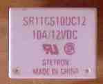
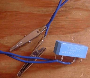
Relay Information for StabilizersThe information that follows is the result of my experimentation with a large variety of relays that were used with the stabilizer. The first set of relays below all worked. The one of the left was too large for practical use, the main reason being its heavy weight. The one on the far right was the first one used with the stabilizer and was shipped in the first kits. Continued tests found another one that worked a lot better, but it is not pictured here. Next are a set of reed relays that did not work. They did move the frequency of the relay but not enough for effective stabilization. Some small relays did a good job. A couple I tested are shown. If you have a really good VFO that shows minimal drift, these relays can be effective stabilizers. A simple test setup consists of a couple of clip leads with alligator clips. A voltage variable power supply is used. Vary the voltage between 2 to 6 volts to get an indication of the range of the relay. Or check the resting voltage of the output of the stabilizer and vary the voltage two volts above and below that point. |

|
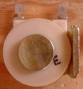
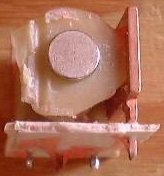
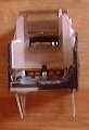
When the switching assembly is taken off, the relay should look like the stripped ones above. A metal rod should be in the middle of the coil, and a thick flange along one side. The magnetism that flows between the rod and the flange is utilized to control the frequency of the VFO. The relay on the left is larger than a T68-6, and pulls the VFO frequency 4 kHz with a 4 volt change (10 MHz). The relay supplied on the right was the first relay supplied with the kit. The third relay is about the size found in automobiles. If you want to experiment with different relays, check out Radio Shack and automobile parts stores. |
|
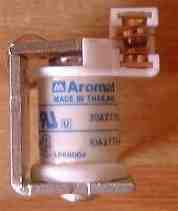
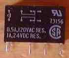
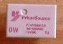
Notice that the switching parts are along the side the coil, instead of off one end. The center of the coil is hollow with flat switching pieces inside. This type of relay is not recommended for stabilizer use as it does not have a break in the magnetic field that can be utilized. It is easy to get fooled and buy a reed relay by mistake. The packaging of some small relays that will work is almost identical to the reed relay above.  A very common reed relay.
|

|
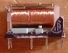
The relays are shown with their switching assemblies still intact. The switching parts are removed so that the center rod in the coil and the flange can touch the wires on the toroid. |
|
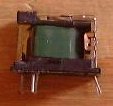
A simple test setup with two wires soldered to the coil pins and clip leads to attach to the Stabilizer board. The relay can be held onto the toroid with a rubber band to test range. The reed relay above is used in the kit at the bandpass filters. It had a range of about 500 Hz, 4 volt change, at 10 MHz (T68-6 toroid). |
Send E-Mail || Amateur Radio Receivers || Electroluminescent Receiver || Back to Frequency Stabilizer - Magnetic Coupling
