
To learn about the Bandpass Filters, read the
Circuit Details - Varicap Tuned Bandpass Filters
before building this section.
|
The IR LED next to the 20 meter bandpass output relay is not installed. Removal of this IR LED is no problem as it is in parallel with the 20 meter bandpass switching LED and its removal increases the available current to the switching LED. |
|
This section uses all the T50-6 (Bag 4) cores in the kit. The wire length will give you plenty of extra on each end. Start with 1" of wire on the end you use to begin winding. After winding, scrape the enamel off the wire on the ends as close to the toroid as possible and tin with solder. Pre-tinning the wires must be done to get a good connection on the board. Wind the coils as follows: ____2 - 8 Turns, wire length 7" |
|
Insert all the components that have their values inside the footprint. They are the following:
____9 - .01 capacitors Solder Resistors:
____2 - 1 meg (Bag 4), Next to the LEDs at the relays on the right side. Capacitors (Going left to right on the board):
____2 - .001 caps (Bag 5), Next to the 29 Turn toroids on each end of the 40/30 Filter. Orange, small square, marked "102". Ones with short leads, put in standing up as they have a slightly shorter profile. After soldering, bend down at a 45 degree angle. ____1 - 3.3pf NPO (Bag 4), Located at the text 20/17. Orange colored, small square, leads flared out, labeled "3R3 D", or short leads, grey with black top, labeled "3R3" (R looks like a P).____1 - 10pf NPO (Bag 5), Located at the text 40/30. Small round capacitor, black top, labeled "10", or Orange colored, teardrop, labeled "100, A1J".
Solder Other Parts:____3 - 1N914 diodes (Bag 4), Black band, be sure to match the band on the diode to the band on the footprint. Bend the leads about 1/8" away from the body of the diode for easy insertion into the PCB. |
|
____2 - IR LEDs (Bag 4), Smoky colored, on a cardboard strip, do not cut the leads off the strip, tear the IR LEDs off the strip and clean the bottom of the leads. Mount as high as possible, then aim to the appropriate photo receiver. ____2 - Photodiodes (Bag 4), Small square part with a tiny bubble on one side. Be sure to match the bubble on the part to the bubble on the footprint. Mount as high as possible straight up.Solder 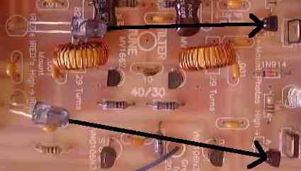
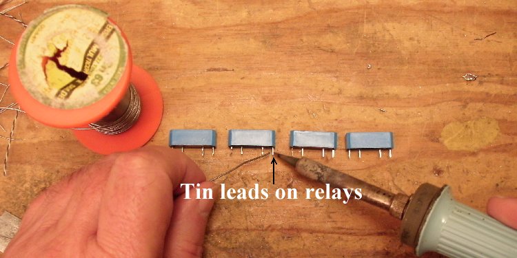
Both IR LEDs are located to the right of the output relays on the left. Both Photodiodes are located to the left of the input relays on the right. See picture above. The IR LED located to the left of the output relay on the 20/17 Filter is not installed. Picture Solder ____2 - MV2115 (Bag 5), Be sure to match the flat of the component to the flat on the footprint. Next to the 15 turn coils in the 20/17 filter. Flat of part is colored light blue, marked "MMV 2115".____2 - MV1662 (Bag 5), Be sure to match the flat of the component to the flat on the footprint. Next to the 29 turn coils in the 40/30 filter. Flat of part has a red line on top and a white line on the bottom, no markings on part, two leads flared out halfway down. Solder ____2 - VN0106N3 (Bag 2), static sensitive part, touch a ground wire before removing from the bag. Match the flat of the component to the flat on the footprint. Spread the outside leads slightly to fit the footprint. Marked "SI N, 0106, 8302".____2 - LEDs (Bag 3), Red color, at the left side of the relays on the right. Match flat of the LED to the footprint. The short lead is on the same side as the flat. Note: If you ordered the Super Bright LEDs, they can replace these LEDs. Use different colors so band identification will be easy. See Modifying the LEDs. ____2 - IRFU220 (Bag 2), Note thick black line on footprint, the heat sink on the part goes over the thick black line on the footprint. Marked "FU220, IR 625T,32 03" Solder ____4 - Blue Relays (Bag 4), Be very careful with the part as the pins are fragile. Do not bend the pins when mounting/soldering to the PCB. Orientation does not matter, inner pins are the coil, outer pins are the relay.Important Blue Relay mounting information! 1. Clean and tin the pins with solder before mounting on board to ensure a good solder joint. The pins can be difficult to solder without pre-tinning. |
|
2. Be sure to mount the relays flush with the board. If mounted slightly off the board, the relay will flex back and forth while handling the board, and break the pins between the relay and PCB. 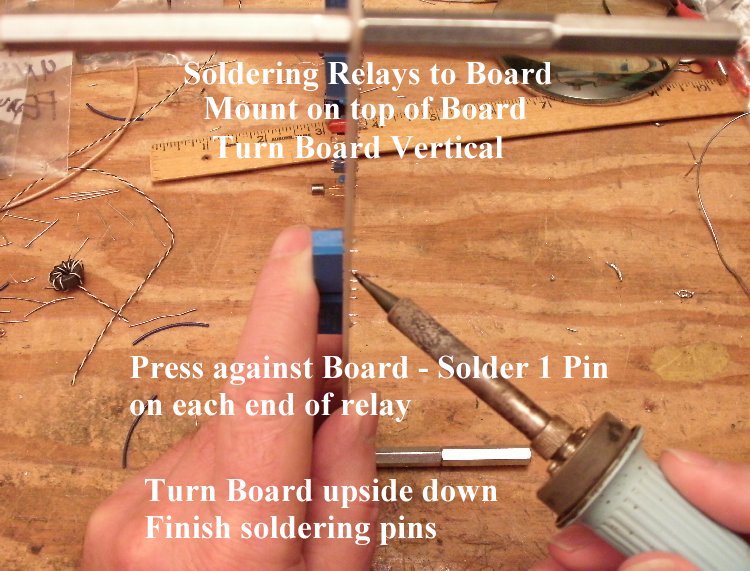 Solder one pin to the PCB, then hold the relay against the top side of the PCB and remelt the soldered pin to set the relay against the board. Then solder the other pins. Solder ____2 - 15 Turn Toroids, mount on the 20/17 filter. Solder ____1 - SPDT Miniature PC Mount switch (Bag 5), There is a switch footprint in front of the Bandpass Filter. There are two hole patterns. Mount the switch in the holes that fit the switch in Bag 5. Picture Solder  Solder  ____1 - 100K Panel Mount Potentiometer (Bag 6) (Picture), The three holes labeled "Filter Tune" should accept the pins of the potentiometer supplied with the kit. ____Bend the outside solder lugs inward slightly and crimp the solder lugs with a pair of needle nose pliers a little bit so they slip through the holes. Picture ____With a knife, fine grit sandpaper, or a screwdriver tip scrape two spots on the upper sides and tin with solder. These are used to solder ground leads from the PCB. Picture ____After inserting the pot, bend the outside solder lugs backwards onto the solder joints of the resistors. Solder the lugs onto the leads of the resistors. Make sure the lugs are not touching the ground plane just above the solder pads. The lugs will be extending over the ground plane. Picture ____To help secure the pot and ground the case (the case can pick up unwanted RF), run wires from the ground holes on both sides of the pot to the case of the pot. Then solder the ground leads to the pot and to the ground plane underneath the board. Picture ____Piece of Hook-up wire 2 3/4" long. One end goes to the FILTER TUNE circle in the middle of the bandpass filters and the other end to the center pin of the pot. Place and solder the wire underneath the board. Picture Solder  Note: The two connected arrows at the bottom left side where the wire is attached indicates where a short will occur if a spacer is placed in the hole noted by one of the arrows. If you put a spacer in this hole, the trace indicated by the other arrow will have to be trimmed to prevent a short to 12 Volts. Solder |
To learn about the TV and FM Filters, read the
Circuit Details - TV & FM, Broadcast Filters
before building this section.
To learn about the RF Amplifier, read the
Circuit Details - High Level RF Amplifier
before building this section.
|
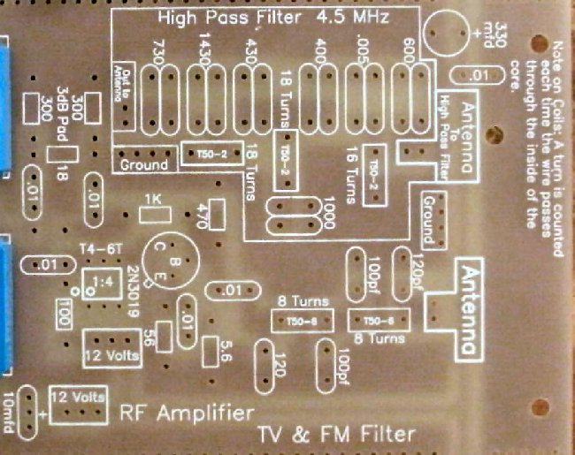
The 4.5 MHz High Pass Filter is optional. The parts for the High Pass Filter are not included in the kit. If you live in a large metropolitan area where several high power AM stations or nearby amateur radio stations are present, you might consider installing the parts. Check out TV & FM, Broadcast Filters for information. Insert all the components that have their values inside the footprint. They are the following:
____6 - .01 capacitors (Bag 3) Resistors:
____2 - 300 ohm (Bag 5), Located at the 50 ohm pad above the Minicircuits T4-6T 1:4 transformer. Solder Capacitors (Going left to right on the board):
____2 - 120pf NPO (Bag 5), Next to the 8 turn coils. Orange colored, teardrop, labeled "121". Solder Other Parts:
____1 - Minicircuits T4-6T transformer (Bag 4), Match the dot on the part to the dot on the silkscreen. The dot on the outside of the footprint will let you double check to make sure the dot is in the correct place after it is mounted. Place the gap of the heat sink directly over the tab of the transistor. The tab will be clearly seen through the gap in the heat sink. The heatsink will be a tight fit on the transistor, so be careful, a small screwdriver may be needed to spread the heatsink in difficult cases. Note the tab on the transistor and match it to the tab on the footprint. Position the bottom of the heat sink even with the top of the T4-6T transformer. Do not mount the transistor flush on the board. Solder ____2 - 8 Turn coils on T50-6 toroid, mount in the TV & FM Filter. Solder |
|
____Place the PCB in front of a bright light. If you see light shining through any of the soldering holes, you missed a solder connection. |
Send E-Mail || Amateur Radio Receivers || Electroluminescent Receiver || Construction of the Kit || Back to SWL Instructions
