To fill some of my Winter hobby time, I decided to build a very portable QRP rig. I like to build some of my own equipment, and prefer to use kits when they are available. I have recently had my interest in CW rekindled, and enjoy being able to operate portable, usually in combination with other hobbies.
The Rockmite, from Small Wonder Labs, has been around a while, and combines a fairly simple and easy to build design with some very useful operating features. It is crystal controlled for one frequency, which is both a limitation and a design asset. You are limited to the one frequency, but by optimizing for that one frequency you get some very good receiver performance. There are simple ways to modify the kit to allow the crystals to be changed, and I may look into modifying later to do so. Initially, after consulting with a friend who may also be building one, I settled on a kit with 7030 KiloHertz crystals, which is the 40 Meter QRP calling frequency.
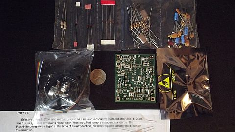
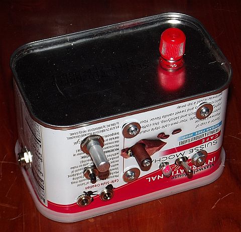
The Rockmite kit is just for the circuit board, with an accessory kit available with connectors, switches, and such. Mounting and enclosure are up to the builder. The basic Rockmite board will fit easily into an Altoids tin, but I wanted to include everything in one package. Of course, the next setp is to decide exactly what "everything" includes. At minimum for my project, that will be the transceiver board, suitable batteries, and an antenna tuner to allow use of end-fed half-wave antennas. I plan to build the whole thing into a flavoured instant coffee tin. I will update with more on the final installation as it progresses, but wanted to start this by detailing my experiences with construction of the Rockmite board.
Small Wonder Labs was run by Dave Benson, K1SWL. He had several interesting kits and products for hams, some of which have been sold or transferred to others when Mr. Benson retired. Several things drew me to the Rockmite, including a simple design, the time it has been on the market and the number sold, and the large online community of users, which has a large data base of construction and operating tips, mods, etc. I subscribe to the Rockmite group on yahoo, and have researched a number of sites with information and examples. I will add a list of relevant links at the end of this page.
One major advantages of building a Rockmite kit is the very affordable price. My kit was just $29 dollars, plus $16 for the optional "connector and control" accessory kit. I have a hard time opening Icom HF rig and playing around with the design, partly because of the cost and partly because of level of manufacturing detail. It just isn't meant to be tinker-friendly. On the other hand, a radio that I assembled myself, and that i understand thoroughly, can provide a lot of opportunity for applying mods, redesigning, and generally tinkering around with its circuitry. The worst case, if I seriously goober it up beyond repair, is to order a new $29 dollar kit and start over.
In spite of the small size, this little transciever has some pretty impressive features. An 8-pin PIC processor is used to control the T/R offset and provide an iambic keyer that will work with paddles, or a straight key. The reversable T/R offset is 700 hz, and provides a built-in sidetone, as a bit of the transmitted frequency is coupled back to the receiver. A crystal is used to provide the basic frequency for the oscillator, with a second crystal on the same frequency used to narrow the receiver front end. The single board provides a 500mW transmitter, a direct convertion reciever, and automatic full-QSK T/R switching.
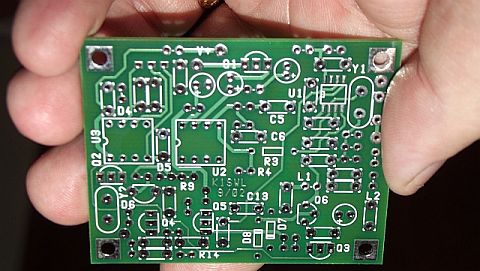

As recommended, I started by soldering on U1. Next I put on the two IC sockets and moved on to installing all the capacitors and three inductors. By installing a few
components at a time, scattered around the board, it wasn't hard to make quick progress. I avoided putting in parts that were bunched up, rather putting in a few at a time
that were spaced out a bit. This kept the leads far enough apart to solder and trim them easily.

After a second session the next night I had the board completely populated.
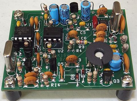
Another area that requires some care is installing the PA transistor, Q6. You need to attach the heat sink before installation and then ensure as it is placed on the board that the heat sink doesn't contact any resistor leads. I added 10mm insulated standoffs to help with airflow around board and they came with screws and washers to mount them to the board and case.
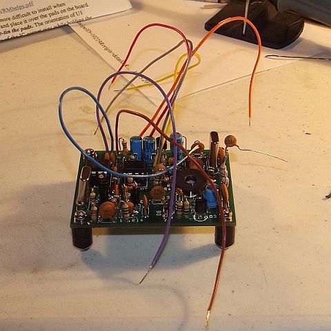
I soldered in wires for the various connections to allow testing. Note the capacitor with the lead extending to the right, which is the antenna connection. This
capacitor and an inductor were supplied on a supplemental sheet. they form a series resonant circuit to reduce spurious emissions, and you should ensure you install them.
With the test leads soldered on it looked like the kit was having a bad hair day...
The enclosure I am going to use is a coffee tin about 2.5 by 2.5 by 4 inches. This should be plenty of room to include a small tuner, batteries, and voltage
regulator and filter.

UPDATE April 12, 2012
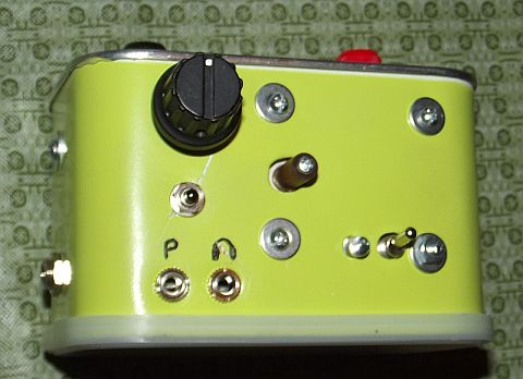
I mounted the Rockmite board on the side, a bit more centered than it is in th photo above. The controls and LEDs are on the side opposite the one the main board is mounted on.
This is the same side where I mounted the tuner, with its controls available. Antenna connection on top and the power connector on the end. The phones and paddles on the left under the Rockmite gain pot and push button.
The opening in the tin is on the bottom with the plastic lid acting as a non-skid base.
I mounted a voltage regulator on the end above the power conector. I did drop the idea of internal batteries, but this will keep my power options open, including a small solar panel.
Since I plan to use a simple wire antenna, I built in a great little tuner, with SWR indicator bridge from Better QRP Kits.
I also built a second one of these tuners for general QRP use, and there is a separate article on my Ham Projects page for the tuner build.
The two 1/8" jacks are for the paddles ("P") and the headphones. Just above is the push button switch to select receive freq and enable paddle speed setting. The large knob is the gain control. The small knob is the tuner capacitor; the toggle switch is for tune/operate with the tuning LED just to the left. The power jack is on the left side, and the antenna terminals are just visible at the top. The photo above this one did not have the ground terminal for the antenna.
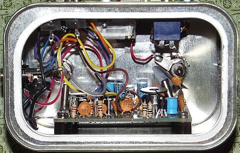
Inside the Rockmite board is mounted on the back side of the tin, and the tuner board on the front. the output of the Rockmite is connected tot eh tuner input by the series resonant circuit supplied to reduce spurious emissions. This is the bottom view with the tin on its back.
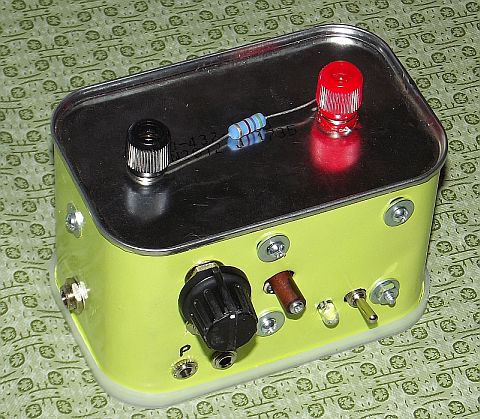
In the final form, the coffee tin contains the transceiver board, the End-Fed Half-Wave Tuner board (with SWR indicator bridge) and a basic voltage regulator to limit the voltage to 12 volts DC. This photo shows the 4.7 KOhm "dummy load" resistor still attached. With it the tuner tuned very easily, and the code sould be heard on my IC-718. I may modify the sidetone volumn, but that can wait for a few actual contacts, which should be coming shortly.
If you have comments, suggestions, or know of really good Rockmite information sites, please e-mail me! !
Last updated 6/15/18