I have always liked to build some of my own ham radio stuff, and tend to be on the cheap side. So, when I ran across a simple, repeatable, method of building "Cheap Yagi" antennas from Kent Britain, WA5VJB, that actually perform well, I couldn't resist trying it out. I have been wanting an antenna to work the FM-Sats, like AO-51. This simple yagi design seemed perfect, so some experimenting was in order. I never like to re-invent the wheel; I'd much rather follow in the footsteps of good practical designer like WA5VJB. If it didn't work well, or I just didn't like it, I could toss it or give it away. It turns out that they worked better than I expected!
The basic approach to this design was not to maximize gain, but rather to make for efficient impedance matching so the feedpoint can be fed with 50 coax. The driven element impedance was worked out and the spacing of the parasitic elements was adjusted to bring the impedance within an acceptable range.
The difference from most yagi designs is the feed point matching system. Homebrew gamma matches are finicky, hard to reproduce, and hard to tune.
Any variation in materials can mean extensive "cut and try" tuning, and I just don't have the patience for that.
I have always liked the "KISS" concept--Keep It Simple, Stupid. Many popular antenna designs are difficult to repeat, or don't have great performance, or both.
The "role-up" twin-lead J-Pole is a perfect example. You see a lot of versions with very different dimensions, mostly due to the wide variations in individual materials in these antennas.
Someone builds one, keeps playing with the feed point and length until they get reasonable performance, and publish the resulting plans to the world.
Then other people try to replicate it, have to go through the same tuning process to get a usable antenna, and then publish their own plans for "the correct" dimensions.
The problem is the interaction between the element lengths and feedpoint impedance. Each antenna has to be custom fitted to work well. Even if you get one of these to work as well as it can, it is still a half-wave antenna with performance approximately identical to a simple dipole or ground-plane antenna.
The yagi antenna design by WA5VJB was intended to be cheap, easy to build, and repeatable. The antenna range performance doesn't quite measure up to the "serious" yagis designed by fanatics who publish dimensions precise to four decimal places. Then they have to find a reliable way to match the impedance of the optimal gain antenna to real-world feedline, which is usually the tricky part.
I understand their motivation--to squeeze every fraction of a dB out of a design. I work with engineers who love a high degree of precision for everything. Of course, being a technician I know that "good enough" really is good enough. If my objective is to be full-quieting into a repeater where I am a bit scratchy with a rubber-duck, I know that "ball-park" is good enough. And these antennas are definately good enough for my uses.
If you want to build an antenna designed to a micrometer level of precision, there are plenty of sites with designs and tutorials on how to design like this. I hope you have fun doing that!
Of course, I do like to play around with a good design to see if I can make it easier, cheaper, or better. So I tend to adapt to materials, tools, and skills that I have or can get easily.
With these yagi designs I basically just altered the construction a bit.
I wanted the "boom" to be more rigid, so I used 1x2-6' pine from my local home center. They are not too warped, and cost less than $2. You can use the whole piece for a longer antenna, or cut it into two or three pieces for shorter ones.
Rather than use heavy-gauge, solid, copper wire, I picked up a roll of the stiff 14 gauge aluminum wire they use to support the frames for drop-ceiling tiles. About $18 for 150 feet, which will make a lot of VHF antennas (even if you have to toss the occasional piece that you cut too short...).
The WA5VJB yagi used a "half-folded" driven element. Like a folded dipole, but only on side is folded and the other side is just a single wire. This is fed with 50 ohm coax, with the shield at the center of the long side of the driven element and the center conductor on at the end of the short side. This is not eas to describe, but easy to see in these photos.
Next comes the need for a way to attach the wire elements to the boom. I do have a drill press and could have drilled holes in the boom for the wires to go into. But, I found it easier to adjust, and just plain easier, to clamp the wire on with three pan-head screws and flat washers.
Two screw on one side and one on the opposite side allows the washers to clamp the wire very solidly. The sheild of coax has a forked lug under the screw for the clamp on the long side of the driven element.
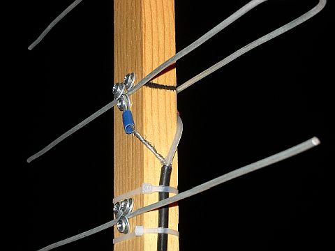
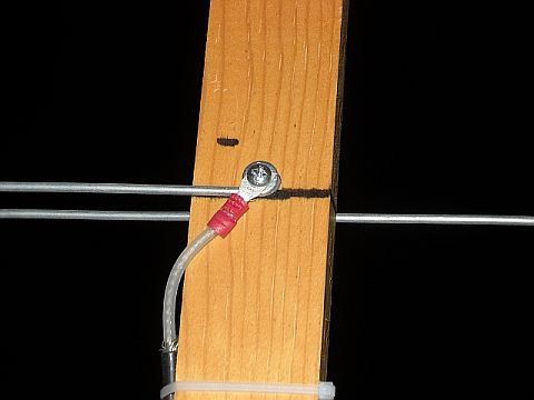
The coax center conductor also has a forked lug, which is secured under the screw holding the short end of the driven element to the boom.
This end has a loop bent in to fit around the screw better, in the plane of the boom.
Using the forked lugs allows the same pieces of coax to be used with multiple version of this antenna, since the coax patch cable I cut in half is the most expensive component in this antenna.
Simply strip and lug each half, so you have cables for two antennas.
Note the jacket is stripped off about three inches and then the center conductor is just stripped enough for the lug.
All in all, this makes for a very simple yagi design, and a very easy construction project. Yes, I can visualize an asymetrical pattern because of the feed, and probably lobes all over the field if you measured on an antenna range. On the other hand, when talking to a buddy with a five watt HT and a homebrew 1/4-wave groundplane on 223.5, over a distance of about 12 miles, the three element 220 yagi in the top photo caught a very quiet signal. When I switched to a 5/8-wave mobile antenna on a steel patio table the signal was readable but scratchy. He reported my signal strength went up from S5 to S7 with the yagi over the mobile. I was using my DJ-280T with about 4 watts out (and no S-meter to quantify received signal strength). I could easily get into repeaters about 8.5 miles away on low power (1 watt ) with full quieting. I need 5 watts watts with the mobile 5/8-wave antenna.
The SWR, after cutting twice for about 1/4" total off the single side of the driven element was barely a wiggle on the reflected power needle, and range to about 1.4:1 at 222.2 and 1.6:1 at 224.9. I used an MFJ-862 for all the SWR measurements on these antennas.
The element lengths and spacing for this antenna came straight from WA5VJB:
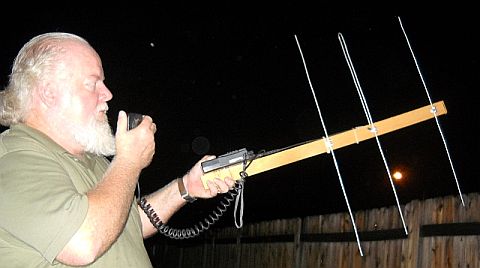
The 220 antenna was my first attempt, since it is small enough to be very easy to build and use, but the frequency isn't so high that tuning becomes touchy. It turned out to perform really well, and I use it every week to check into a 220 net. It is also small enough to keep in my Jeep in case I am somewhere that a 5/8 mobile antenna just doesn't quite do the job. The photo at the top of this page shows my using this 220 antenna, with the HT zip-tied in place and using a speaker/mic.
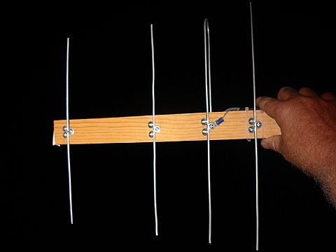
Following my success with a three element 220 antenna, I decided to try a four element 440 version. I can get to a couple of repeaters 8.5 miles away with a rubber duck and five watts, but a repeater about 22 miles away was outside my HT's range.
So I built one that WA5VJB indicated was for 440 FM use. I discovered an issue with it. The dimensions in the pdf file cited at the beginning of this page for the parasitic elements is fine, but the driven element didn't work for me at all. It calls for a driven element a total of 12 inches long, but i had to scrap that one and go to 12.5 inches. This dropped into a usable VSWR with very minor tuning. The final dimensions for mine are:
I tried this antenna with my VX-5R, and could easily work the repeaters 8.5 miles away on low power (.5 watt) with full quieting, where a rubber ducky needed five watts. The repeater 22 miles away was easy to work with five watts and the yagi being hand guided in my backyard.
Since these antennas worked so well, I decided to try a two-meter/435 combo for AO-51. This presented a couple of new challenges, so I will write another article about that part of the project.
In summary, if you want an easy to build "no-worries" yagi for VHF or UHF, then download "Cheap antennas" from Kent Britain, WA5VJB, and start building! Let me know how it turns out.
Be sure to check out his other articles:![]()
Last updated 6/15/18