Removing the lock mechanism from a GE Master 2 Mobile
by
Ralph Hogan W4XE
In my repeater conversion of a GE Master 2 mobile,
I remove the key lock mechanism. I bring out the controller cabling and
receiver RF cable through the hole left by the key lock mechanism.
I’ve heard tales of hams busting off the slider
mechanism in order to get the lock out. Don’t bust the slide bar! It
just takes a paper clip!
It took me a while my
first time to get it out, you have to be part lock smith which I am not.
I’ve detailed the steps below. In less than 5 minutes, you can have it
removed.
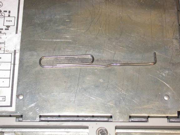
Take a large sized paperclip and unbend it out in
the shape below. Make a 90 degree bend at the tip, about 3/8" long.
-----------------------------------
(_______) | 3/8" long
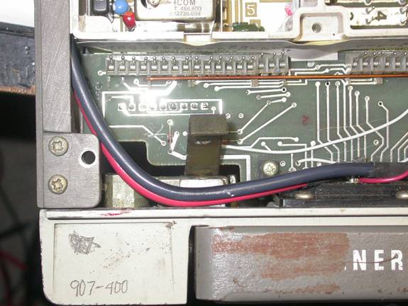
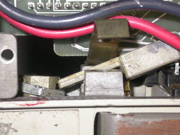
Now remove the top screw holding in the bracket
which retains the PA red & black power cables. You may have to unplug
the F1 channel element to get a good angle for the screw driver.
Now bend the bracket out of the way. This is
easier than tearing the radio apart to remove the second bottom screw
holding the bracket in. If you are not keen on bending, you can very
carefully back out the bottom screw. However it has clearance issues
with the system control board PCB. If you can loosen it some, the
bracket will swing out of the way. It’s up to you to bend or not bend.
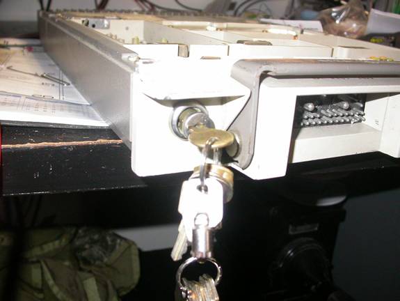
Now insert the tool you’ve just made into a tiny
hole on the side of the lock mechanism. Insert on the side shown. There
is another hole
on the opposite side, but it won’t work. Insert the
stock GE Key, but don’t turn the cylinder.
Here is the tricky part. Apply pressure to the
tool, driving the end of the paperclip into the hole. Now slightly
wiggle/twist the GE Key around and with a pulling motion. Don’t turn the
key very much in this process. Eventually the key and cylinder will pull
out of the lock. Don’t get discouraged if it doesn’t come right out.
You’ll get the hang of it. What you are doing is depressing a spring
loaded ‘C’ clip on the end of the cylinder. (See photo below). The ‘C’
clip is what is holding the cylinder in the lock mechanism. By dressing
it, it allows you to remove the cylinder. Note the position of the key
while it is being pulled out.
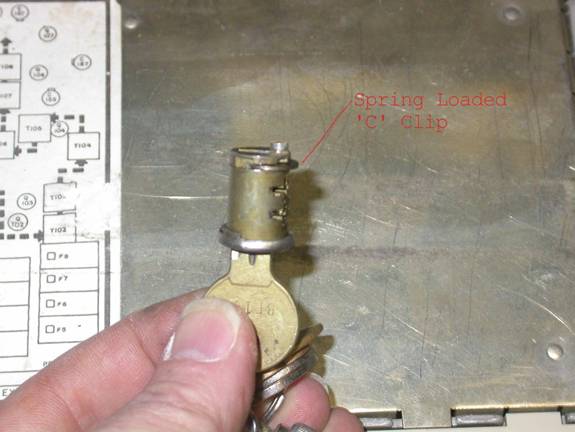
Here is a close up of the lock cylinder removed.
Note the ‘C’ clip on the end of the cylinder. If you turn the key too
much during the removal process, the end of the paperclip won’t be on
top dead center of the ‘C’ clip.
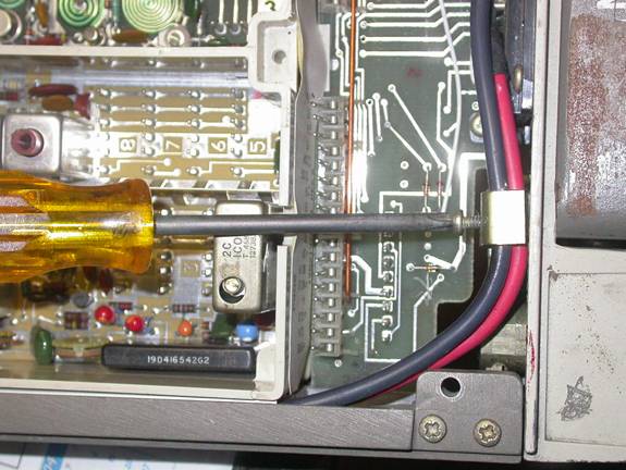
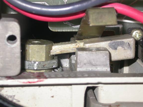
Now it is time to remove the remainder of the lock
mechanism. The lock is held in place by a large nut. I’ve used long
needle nose pliers before to loosen the nut. In stubborn cases, you have
to persuade it a little. Take a flat head screwdriver ( one you don’t
like very much) and position it at the edge of the nut.
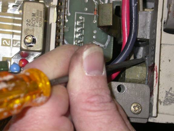
Tap the top of the screwdriver with a small hammer.
You are pushing against the corner of the nut at an angle. Usually one
good tap or two will free up the nut. At that point it will usually
unscrew easily by hand. Back the nut all the way off. Note: it can’t be
removed because the slider bar is still in the back of the mechanism.
You can now pull what’s left of the lock mechanism
in the key lock hole forward to the front of the radio. This allows you
to angle the slider bar past the front control head connector J901 and
remove the slider bar. Pull out the remainder of the lock, lock washer
and nut.
These are all of the pieces that are removed from
the radio. I keep a cylinder around in the toolbox, just to remind
myself which way the key is positioned during the removal process.

Now bend back the retainer that was holding the PA
power cables and reinstall the screw you removed.

Congratulations, you now have an empty hole.
You can snake the controller cables through this
area. Alternatively, some folks like to install a second SO-239 for the
receiver in this hole. If you mount an RF connector here, this requires
you utilize the front control head connector to get at the signals for a
ham repeater controller. You’ll have to cut a factory control head cable
and wire on a mating controller connector. I’ve done it both ways in the
past. Personally, I don’t like using the stock control head cable, as
it’s bulky and heavy. This requires you use some sort of strain relief
for the cable at the ham controller.

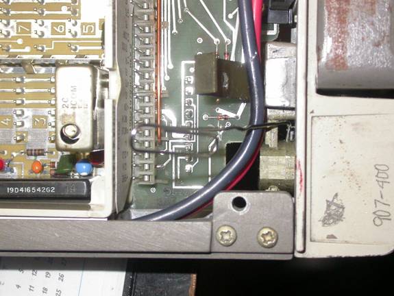
The finished product: A backup UHF repeater in
case the main site hardware has troubles. As a finishing touch not shown
in the photo below, I’ll dress the cables using some of the black
plastic spiral wrap ( available at Walmart or an automotive store) to
dress the shielded audio/control cables from the keyhole to the repeater
controller connector. To the savy reader you’ll notice an NHRC-4M2
installed. In this case, the cables coming out are for a remote base
radio.

A conversion where I utilized an RF connector in
the key-hole location. In this case the first ½ of a split site 6 meter
repeater.

73’s and good luck!
Ralph Hogan W4XE
[email protected]