Revised:
06/06/2007
Update
After writing this article, I came across a lot of additional information. For one, I found that there were at least three different versions of the RCS-4 antenna switch. I have been unable to determine how to tell them apart from the outside. At least that is, all three. One has an internal 12v transformer, one uses an AC wall wart, and one has only two relays instead of three. You have to look inside to tell if you have one of those.
I also found that I could do some additional modification to my three relay boxes to add BIP/BOP operation. The modification consists of re-wiring the board again, and adding two more RF ports (SO-239 connectors). This update will discuss the two relay box, and how to modify it for operation as originally described, and how to modify the three relay box for BIP/BOP. I will also discuss a bit about what BIP/BOP does for the un-initiated.
The Two Relay Box
The two relay box can still be configured for stacking, but is not capable of BIP/BOP control. Below is a representative diagram of the original two relay configuration (Figure 1.). This diagram shows the relay configuration for each antenna position based on the control voltage applied.
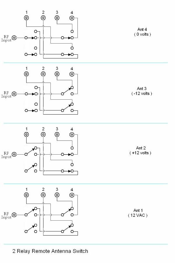
Figure 1.
The box must be disassembled as in the original article, and the board reconfigured to comply with Figure 2 below. As in the case of the original modification (see Feeding that Stack), a quarter wave 75 Ohm jumper is connected between the old antenna ports 1 and 2 . As configured in figure 2, position one will be High, position 2 will be Low and Position 3 will be the Stack Position 4 will be be connected to the High antenna, but will appear as 100 Ohms as there is no quarter wave series section applied.
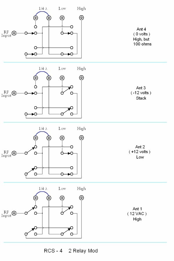
Figure 2
BIP/BOP Mod
The BIP/BOP modification can be performed to the three relay version, but not the two relay version. Referring to the original article (Feeding that Stack), you must add two SO-239 panel mount UHF connectors to the relay box. Looking at the unit from the front, I mounted mine at the rear right and left sides of the bottom of the chassis. The circuit must be modified as shown in Figure 3 below. In addition, for the simplicity of drawing the schematic, K1 is the center relay with K2 on the left and K3 on the right. Note that the apparent unused set of contacts from the original mod (actually used to turn off AC to K2 and 3 when K1 is energized, must be rewired. This configuration energizes all three relays in the antenna 1 position (LOW) and you must add a jumper from the bottom of the choke to the coil of K2. You must also add about a 100 MFD @25vdc electrolytic across K2 and K3.
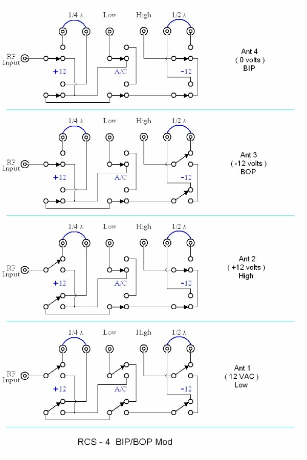
Figure 3.
A half wave section of 75 Ohm cable is added to the right hand ports which is needed to reverse the phase by 180 degrees. As can be seen above, position one connects the Low antenna, position 2 connects the High antenna, position 3 connects the antennas in parallel and out of phase (BOP) and position 4 connects the antennas in parallel in phase (BIP).
A Little About BIP/BOP
BIP/BOP refers to feeding antenas Both In Phase (BIP) or Both Out of Phase (BOP). The advantage of this feed arrangement combined with feeding either antenna alone is that it provides 4 different takeoff angles. The antenna system can thus better match the propagation angle for a particular time, optimizing performance.
The propagation angle for any given path can vary greatly depending on time of day and solar flux. As the time of day changes, so does the ionization of the ionosphere. In addition, the height of the refracting layer (E, F1 or F2) changes. These factors change the number of hops for a given path and the refraction angles resulting in changes to the propagation angle. As an example, 20 meters will normally open on a very low angle path, often a single hop. As the sun rises to it's zenith and the ionosphere charges to maximum, the refracting layers lower and become more efficient. Signals get much stronger, there are normally multiple hops, and the angle gets quite high. Throughout this process, matching the propagation angle maximizes system performance.

Figure 4.
As can be seen in figure 4, there are 4 different takeoff angles. Adjusting the heights of the antennas can optimize the angular differences as well as changing the stacking gain.