OOPS:
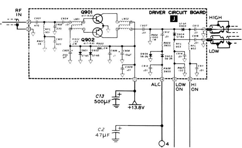
C2, a 47 μF Tantalum capacitor, across pins 3 and 4 of board J, Driver, is consistently shown wired incorrectly.
The ALC voltage is negative and the positive lead of the Tantalum capacitor is wired to the ALC pin. OOPS!
I can confirm that most HW/SB-104 transceivers have this capacitor wired wrong! Yes, I have had to replace a shorted C2.
C2 should be removed and discarded and a new 1 μF at 50V aluminum electrolytic be wired in its place. Be sure to connect
the negative lead of the new capacitor to pin 4, ALC, of board J, Driver. The positive lead goes to pin 3.
But the ALC pin has +1.3 to +1.5 volts on receive when in low power mode! The ALC line is negative going voltage to turn off Q303 which causes
higher positive voltage at the gain control pin of IC301, a MC1350. Higher voltage at gain pin reduces gain of MC1350.
A normal polarized aluminum electrolytic can handle small reverse voltages of about 1.5 Volts. A Tantalum capacitor is destroyed
by reverse voltage -- it shorts! As shown, C2 would have considerable reverse voltage if the Driver produces normal RF output of about 10 Volts in high power mode.
Many of the serious problems that plagued the early SB-104 model were resolved by the time the HW-104 was made available. Many
of the Service Bulletins and Modification Kits (SBM-104) apply only to the earlier original SB-104 and not to the HW-104.
SB-104 circuit boards are green fiberglass epoxy FR-4. HW-104 circuit boards are orange/brown phenolic paper FR-2.
Many units may be already modified per the instructions from the following resources:
[Improved Receiver Performance for the Heathkit SB-104A],
Ham Radio, April 1981
(Numerous errors in this article)
While modern substitutes are available for most electronic devices used in the 104 series, there are a few obsolete devices that do not have drop in replacements:
- B - Transmitter Audio and Regulator = MFC6030 regulator IC
- H - Power Amplifier = Microsemi PPC 2N6456 (NSN: 5961-01-103-7288) or CTC CD-2664A or TRW PT5757 RF power transistors (Originally was Acrian S30-12A)
(Possible subs include several MRF devices with different mounting arrangement.)
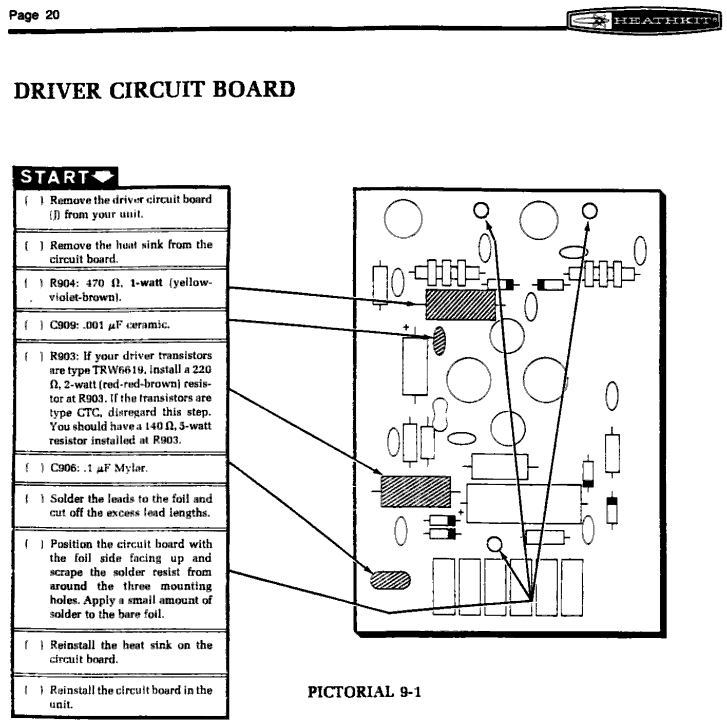
- J - Driver = TRW PT6619 (NSN: 5961-01-107-3380) or CTC CD-3342 RF transistors
(Possible subs: 2N4127, Russian KT920A, 2N6081 and others)
- NOTE: CTC ==> Acrian, Microsemi ==> Microchip, What happened to TRW semiconductors?
There are many SB-104/HW-104 out in the used market that probably never worked at all. They can be put in service with varying amounts of effort. Others were used until some electronic part failed -- probably the regulators on the B (Transmitter Audio and Regulator) and/or the Final H (Power Amplifier) board.
Here is a list of steps needed to bring a 104 series rig back to life.
-
Remove and check all boards for unsoldered/cold soldered joints, burned components, corrosion, and other damage. Clean and tin the grounded
edges where the board fits in the card guides. Remove the Final H (Power Amplifier) and J (Driver) boards.
-
Improve the regulators
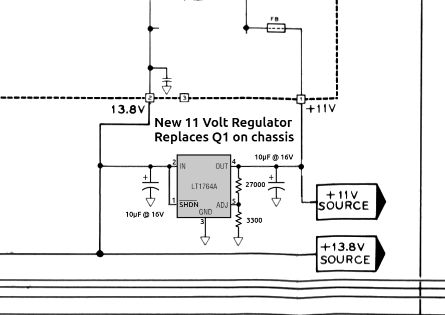
- Replace the flakey, obsolete MFC6030 11 Volt regulator and pass transistor with a Linear Technology (now Analog Devices)
LDO regulator.

- Replace the 5 Volt regulator on the SB-104 with a 3 terminal regulator IC (LM323K for example).
- Remove unused regulator components from the B (Transmitter Audio and Regulator) board.
- The best way to test the low level circuits is by applying power via pin 4 of the power jack. Pin 4 powers everything except the Final.
- If you are lucky all low level circuits should work.
- If you are unlucky refer to the troublesooting section of the manual.
- If the carrier generator oscillators on the E (Carrier Generator and Crystal Filters) board are too low in frequency,
the frequency can be raised by inserting a capacitor in series with the crystal.
- Check for updates from
.
- Updates to the C (Transmitter IF), K (ALC), VFO, and VFO Filter boards are critical to reduce spurious signals.
- Check the Improved Bypassing and Termination Checklist.
- Check Service Bulletins for updates. Note that several of the bulletins are optional and may refer to boards older than the version in the radio. If it isn't broken, don't fix it.
- Check the J (Driver) board for shorted transistors. If OK, update, reinstall and test.
- Check the H (Power Amplifier) board for shorted transistors. If R959 is burned at least one pair of final transistors are not working right.
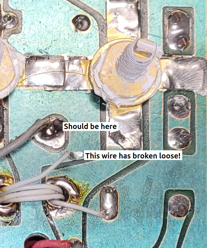
- Resistance checks suggested something wrong with Q954.
- Removed heat spreader -- found loose wire in collector circuit of Q954 at transformer L957.
- Resoldered wire -- proceeding to upgrade and testing.
- While testing, C3, a 47 μF Tantalum capacitor, shorted. Replaced with parallel 0.1 μF ceramic and 1000 μF aluminum electrolytic.
- SUCCESS! 100W output!
BUGS
- Burst Of RF When PTT Is Released (Service Bulletin SB-104-80, December 11, 1978)
- This burst of RF when the PTT is released can occur on all bands. Three
causes of this are:
- A spike on the audio output of board B caused by the +RX mute voltage
applied to pin 2 of IC201B through R212. The solution is to let IC201B
remain active all the time. This is done by connecting R212 to ground
instead of Q-205's collector.
-
The rapid rise of the voltage on the PTT line. This is coupled to the
input of IC201A through the stray capacitance at the MIC connector.
Installing a .05 μF capacitor from B8 to ground slows the rise time enough
to prevent this coupling.
-
The transmitter is keyed for the first time after power is first
applied to the unit. The application of power to the unit causes a charge
to build up on C-646 which, in turn, causes a short burst of carrier output
when the balanced modulator is driven with a signal from the carrier
oscillator. Subsequent keying will not produce the burst. Installing a
6.8K ohm resistor [PN 6-682-12] across C-646 will allow it to discharge.
Then perform the carrier null adjustments.
To prevent the RF burst, make the following changes:
- Remove the jumper connecting R-212 to Q-205 collector. Connect R-212 to
ground.
- Install a .05 μF capacitor [PN 21-143] from B8 to ground.
- Install a 6.8K resistor [PN 6-682-12] across C-646.
- Poor Carrier Supression (Refining the SB-104, QST, March 1982)
-
Difficulty in achieving a good carrier
null in the balanced modulator was caused
by poor carrier-frequency bypassing at the
modulation input port. Replacement of
C646 (a 4.7-μF tantalum capacitor) with a
0.1-μF ceramic capacitor and series-connected 47-ohm resistor produces better
suppression.
- Obtaining A more Logarithmic S-Meter Response (Service Bulletin SB-104-83, November 19, 1979)
- The S-meter in most units is largely insensitive to plainly audible
signals, while allowing slightly louder signals to peg the meter [with
R-534 set for an S-9 meter reading at 50 microvolt signal at the antenna
connector]. To provide a more logarithmic response, perform the following:
- Replace ZD-502 with a 1N191 signal diode [PN 56-26]. Install this diode
opposite that shown on the circuit board, so that it is forward-biased
[cathode towards R-534].
- Two diodes in series may give a better response.
- Set R-534 to S-9 with a 30 microvolt signal.
The meter will register slightly more accurately from S-9 to +30 but will
have little or no action above +40.
Perform this modification only if the customer specifically complains of
this problem.
- Talk Back in SSB
- FIX
- Other Problems
- FIXES
