USDXOCTOBAND
videos
https://www.youtube.com/watch?v=KdeEVT8ZBOo
https://www.youtube.com/watch?v=u6GpqqaDkMY
GERBER PCB MCP28003 & CD4017 WB2CBA
Octoband
to use
MCP28003 enable this line:
//#define LPF_SWITCHING_WB2CBA_USDX_OCTOBAND
1
GERBER PCB MCP28003 & PCA9555 DL2MAN
to use PCA9555 enable this line:
//#define LPF_SWITCHING_DL2MAN_USDX_REV3_NOLATCH 1
Para usar estas placas (MCP28003 ou
PCA9555) com reles
de 5V é necessario alimentar VCC com 5V (não com 12V) e
não usar o regulador de 5V, jumpeando a entrada e a saida.
To use these boards (MCP28003 or
PCA9555) with 5V relays it is necessary to supply VCC with 5V (not with
12V) and not use the 5V regulator, bridging the input and output.
Desenhamos uma PCB para abrigar o OCTOBAND do WB2CBA, Barb.
Mas como o circuito de comando é modular ele pode ser comandado
manualmente por chave de onda, com um botão com o cd4017,
automatico com o
MCP28003 (WB2CBA) ou com o PCA9555, PC9556 (DL2MAN).
Nossas placas (py2ohh)
do USDX
estão configuradas para serem usadas com qualquer destes
modulos.
Resolvemos montar com a Placa usando Atmega e o SN74CBT3253 TSSOP (ou
SSOP).
Usamos na montagem reles do tamanho normal, tipo DIP, e os circuitos de
LPF associados, em modulos iguais aos usados no USDX do mutirão.
Assim a montagem e os ajustes ficam mais faceis de serem feitos.
Portanto os circuitos de LPF e o de controle são modulos, que
são tipo plugin e os circuitos de controle manuais ou
automaticos podem ser usados.
A unica alteração na montagem do USDX, é uma
modificação necessária no modulo SI5351, qualquer
que seja a procedencia do modulo, é preciso retirar 2
transistores e 4 resistores e colocar dois jumpers. Esta
alteração faz com que o I2C funcione tambem para o modulo
de comando dos reles. O modulo do SI5351 depois da
alteração continua funcionando normalmente em qualquer
circuito do USDX.
Esta modificação esta descrita no
site do WB2CBA
We designed a PCB to house the
WB2CBA's OCTOBAND, Barb.
But as the control circuit is
modular, it can be controlled manually by wave switch, with a button
with the cd4017, automatically with the MCP28003 (WB2CBA) or with the
PCA9555 (DL2MAN).
Our USDX boards (py2ohh) are
configured to be used with any of these modules.
We decided to assemble it with the
Board using Atmega and the SN74CBT3253 TSSOP (or SSOP).
In the assembly, we used
regular-sized DIP relays and the associated LPF circuits, in modules
equal to those used in the USDX of the collective effort.
This makes assembly and adjustments
easier.
Therefore, the LPF and control
circuits are modules, which are plugin type. Thus manual or automatic
control circuits can be used.
The only change in the USDX assembly
is a necessary modification in the SI5351 module, whatever the module's
origin, it is necessary to remove 2 transistors and 4 resistors and
place two jumpers. This change makes the I2C work also for the relay
command module. The SI5351 module after the change continues to work
normally in any circuit of the USDX.
This modification is described
on WB2CBA
site
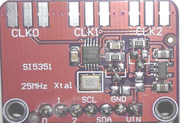
Eu modifiquei, mas tirei somente dois resistores e dois transistores, o
jumper pode ser feito com um fio fino. Sem esta
modificação o circuito integrado de
comutação de banda não funciona.
I modified it, but I took only two
resistors and two transistors, the jumper can be made with a thin wire.
Without this modification the band switching integrated circuit does
not work.
Esquema:
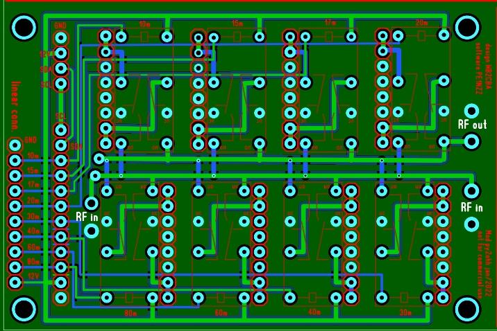
PCB Total
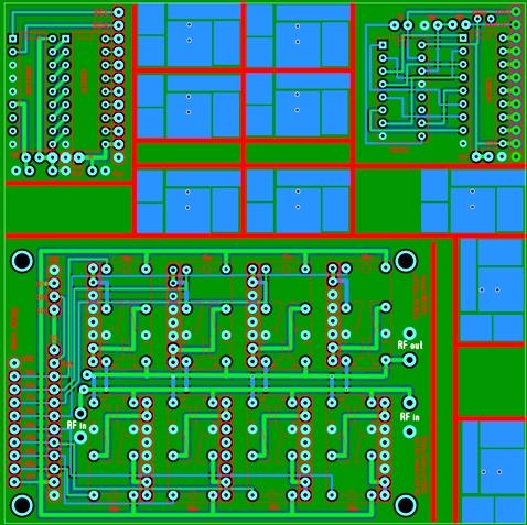
Esta PCB, de 100x100mm, aproveita os espaços de sobra para ser
ocupada por um modulo automatico com o MCP28003, outra PCB com o CD4017
e ainda 9 PCBs para modulos de LPF.
Esta PCB principal, pode ser operada por uma chave de onda para troca
manual de
bandas.
This 100x100mm PCB takes advantage of
the spare spaces to be occupied by an automatic module with the
MCP28003, another PCB with the CD4017 and even 9 PCBs for LPF modules.
This main PCB can be operated by a
wave switch for manual band switching.
Ou com um botão comandar a placa, por encaixe, de comando com o
CD4017, que a cada pulso do botão, muda de banda.
Or, with a button, control the board,
by plugging in the control with the CD4017, which changes bands with
each press of the button.
Este metodo manual de troca de bandas, deve ser controlado por leds no
painel. Os leds devem ser conectados no plug da PCB, em amarelo no
desenho. Este plug tambem pode ser usado, para atuar reles de um LPF de
um
PA, por exemplo.
This manual method of changing bands
must be controlled by LEDs on the panel. The LEDs must be connected to
the PCB plug, in yellow in the drawing. This plug can also be used to
actuate relays from an LPF of a PA, for example.
Outra forma seria como uso do IC MCP23008, que via I2C faz o comando
automatico de troca de bandas. Esta forma automatica tambem esta
prevista em uma PCB por encaixe (modulo).
Another way would be using the IC
MCP23008, which via I2C makes the automatic command of changing bands.
This automatic form is also provided for in a plug-in PCB (module).
Esta placas encaixaveis ou modulos, estão na PCB total.
Estão tambem as placas encaixaveis, dos modulos do LPF, para
cada banda.
Para usar a forma automatica é necessario alterar a
configuração do Sketch do programa. Ativando a Placa
octoband do WB2CBA.
Para ativar a linha
//#define LPF_SWITCHING_WB2CBA_USDX_OCTOBAND
1
basta retirar as duas barras invertidas do inicio da linha
#define LPF_SWITCHING_WB2CBA_USDX_OCTOBAND
1
Compilar o sketch e carregar no atmega ou nano.
Este modulo do WB2CBA que usamos neste USDX 8 bandas.
These plug-in boards or modules are
in the total PCB. There are also plug-in boards for the LPF modules for
each band.
To use the automatic form it is
necessary to change the Sketch configuration of the program. Activating
the WB2CBA octoband board.
To activate the line
//#define
LPF_SWITCHING_WB2CBA_USDX_OCTOBAND 1
just remove the two backslashes from
the beginning of the line
#define
LPF_SWITCHING_WB2CBA_USDX_OCTOBAND 1
Compile the sketch and load it into
atmega or nano.
This WB2CBA module that we use in
this 8-band USDX.
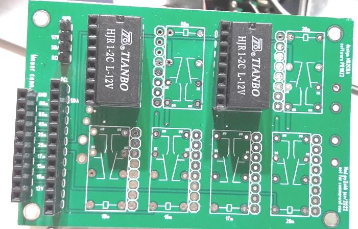
PCB do octoband
Esta PCB tem o tamanho da PCB do mutirão 54x82mm.
Da esquerda para direita temos:
Conector para comando externo, de um LPF de um PA por ex. ou do
indicador da banda selecionada, no caso de comando manual.
O segundo conector é para o modulo de comando CD4017, ou
MCP23008 ou futuramente o PCA9555 (já testado).
This PCB is the size of the task
force PCB 54x82mm.
From left to right we have:
Connector for external control, from
an LPF of an AP, eg. or the indicator of the selected band, in the case
of manual control.
The second connector is for the
command module CD4017, or MCP23008 or in the future the PCA9555
(already tested).
Usei reles de 12V, mas podemos usar reles de 5V alterando a
alimentação e eliminando os reguladores de 5V.
Acima do segundo conector temos a conexão de entrada 12V e terra
e a conexão para o I2C.
As conexões de RF de entrada e saida neste desenho estão
trocadas, mas devem ser feitas com cabo coaxial de 50R fino e
ligações curtas.
I used 12V relays, but we can use 5V
relays by changing the power supply and eliminating the 5V regulators.
Above the second connector we have
the 12V input connection and ground and the connection for the I2C.
Input and output RF connections in
this drawing are interchanged, but must be made with thin 50R coaxial
cable and short leads.
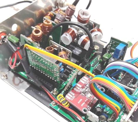
Na montagem deste 8 bandas, usamos nos modulos do LPF, capacitores SMD
COG ou NP0 de 500V ou mais, mas poderiamos usar capacitores de ceramica
ou styroflex de mais de 200V. Usamos bobinas com nucleo a AR, para
mostrar que não é necessario o uso de toroides.
Com toroides é mais fácil de se montar mas não
é fácil de adquirir toroides por aqui.
Lembramos que os LPF do mutirão são do iguais aos usados
aqui.
Os reles de 12V tinhamos em mãos, e são do tamanho DIP.
Os integrados foram comprados via Aliexpress, e os capacitores da LCSC
da China.
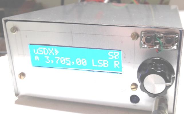
Apos os ajustes obtivemos os seguintes resultados com 12V, de 80 a 15m
5W, em 11 e 10m (até 30MHz) 3,5W. Não optamos por ajustar
pensando em alto rendimento e sim em potencia.
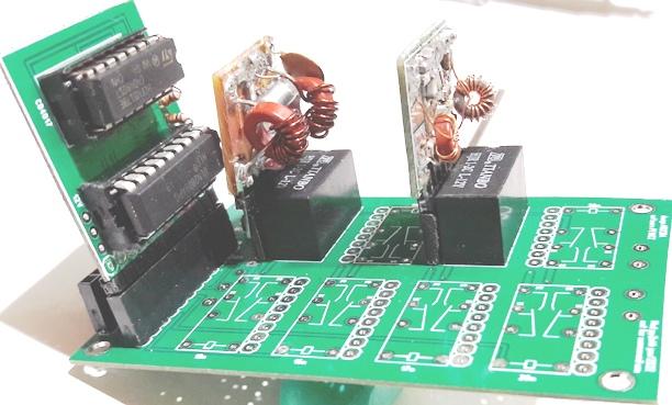
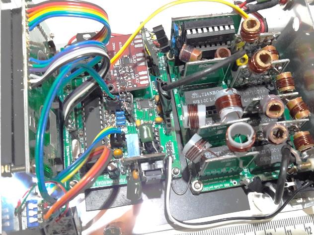
Fotos da montagem :
In the assembly of this 8 bands, we
used in the LPF modules, SMD COG or NP0 capacitors of 500V or more, but
we could use ceramic or styroflex capacitors of more than 200V. We use
AR core coils to show that toroids are not needed.
With toroids it's easier to assemble
but it's not easy to buy toroids around here.
We remind you that the LPF of the
collective effort are the same as those used here.
The 12V relays we had in hand, and
they are DIP size.
The integrated ones were purchased
via Aliexpress, and the capacitors from LCSC from China.
After the adjustments we obtained the
following results with 12V, from 80 to 15m 5W, at 11 and 10m (up to
30MHz) 3.5W. We didn't choose to adjust it thinking about high
performance, but about power.
Assembly photos:
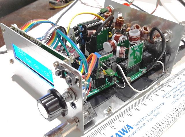
Apesar do tamanho dos indutores, dá para montar em uma caixa
pequena.
Despite the size of the inductors,
you can mount it in a small box.
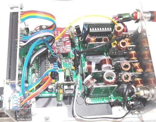
Os circuitos ficaram proximos mas funcionaram perfeitamente.
The circuits were close but worked
perfectly.
Usei cabo coaxial blindado para as conexões de RF.
I used shielded coaxial cable for the
RF connections.
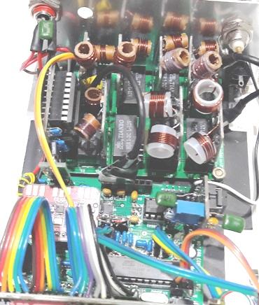
As bobinas enrolei conforme descrito no artigo meu USDX
The coils wound as described in my USDX article
A montagem do USDX é praticamente igual ao do passo a passo, difere
somente no SN74CBT3253, substituindo o 74HC4053.
No artigo passo a passo e meu USDX, são encontradas todas as
informações de montagem e ajustes dos LPF.
The USDX assembly is practically the
same as the step-by-step, only differs on the SN74CBT3253,
replacing
the 74HC4053
In the step-by-step article and my USDX, all the LPF assembly and
adjustment information is found.
73 de py2ohh Miguel (08\2022)