IMPROVED CRYSTAL RECEIVER
FOR THE BTTF 2004
(2004)
KLIK HIER VOOR NEDERLANDSE VERSIE
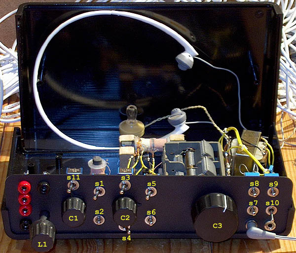
The improved crystal receiver. Instead of the traditional crystal telephone, a Philips headphone
model HS415 was used with the same or perhaps even better sensitivity and much better audio quality!
BTTF contest!
From December 25 to December 31, a contest is organized here in the Netherlands. The name is Back To The Future (BTTF). The challenge is to log as many medium wave stations as possible with a passive receiver.
Click HERE if you want to download the zipped bttf2004log.doc log of the stations I heard in December 2004 with this crystal receiver during that contest. There were 76 different medium wave stations identified, but some more unknown signals were heard.
Click HERE if you want to download the zipped bttf2005log.doc log of the stations I heard in December 2005 with this crystal receiver during that contest.
Click HERE if you want to download the zipped bttf2006log.doc log of the stations I heard in December 2006 with this crystal receiver during that contest.
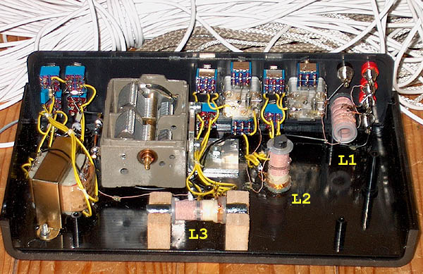
Inside view
Improvements of the BTTF 2004 receiver compared to the BTTF 2003 receiver
This receiver also has the antenna tuner to improve the selectivity and sensitivity.
But it also has an extra L/C combination that can be switched (with S4) as a filter for extra selectivity or as a notch filter to suppress signals from strong broadcast stations. All coils do have litze wire now. The variable capacitor with reduction gear has a calibrated frequency scale, very useful to identify stations quickly.
It is also possible to select a germanium or a schottky diode (S8). Sometimes the germanium is better, sometimes the schottky diode. This experience was different from that with the BTTF 2003 receiver, in 2003 a germanium diode was always better....
The diode detector is not directly connected to a crystal telephone. Experiments showed that the sensitivity is better when an audio transformer is used and that the crystal telephone is connected to a tap of that audio transformer. It is also possible to use a low impedance headphone now. It can be connected to the secundary of the transformer.
During the contest, a Philips headphone model HS415 was used. Sensitivity and audio quality are better than that of the crystal telephone. Only one earpiece is connected, the impedance is 16 ohm and sensitivity 102 dB. Also very good is an Adastra driver unit model 952.207. But it is very heavy. For more information about the transformer used here and the very sensitive Adastra driver unit, see the nice site of Dick Kleijer about crystal receivers http://www.crystal-radio.eu/.
Diagram of the improved BTTF 2004 crystal receiver.
big diagram
Explanation
All coils are standard available coils for ferrite rods as used in broadcast receivers. L1 is a longwave reception coil, L2 and L3 are types for the medium wave. For the 8, 4, 2 and 1 winding taps, extra coils are wound with 0,3 mm copper wire.
L1 and C1 are the antenna tuner, tuning the antenna wire to resonance for maximum sensitivity and extra selectivity.
L2 and C2 are the extra filter. It can be used as a notch filter or as a filter for more selectivity (depending on the position of S4). I used it a lot as a notch filter (mostly the tap on 2 and 4 windings was used, sometimes the tap on 8 windings but the tap on 45 windings was never used).
L3 and C3 are the main selective tuning filter. Thanks to the very good variable capacitor with reduction gear and calibrated frequency scale, it was easy to identify the stations with use of a portable receiver with digital frequency read out. The diode detector can be connected to a tap (at 45 windings) or to the top of the coil. The tap is used above 1 MHz, the top connection below 1 MHz.
After the diode detector, the already mentioned transformer and crystal telephone or low impedance headphones can be found. As the transformer has almost no DC impedance, the 150k ohm resistor with the 0,1 uF capacitor are added so that the DC resistance is more or less similar to that of the AC impedance of the audio transformer. This is important for a distortion free reception. However, for weak signals the sensitivity is better when this DC load is switched off (S9).
Due to the loading of the detector and the antenna impedance, the Q factor of the coils will be reduced from more than 150 to somewhere between 50 and 100. Selectivity will be somewhere between 10 and 30 kHz.

Antenna during the BTTF 2005: to the tree right behind
and then back to the left to a tree with a height of 2 meters
Antenna
The total length of the antenna is 50 meters. The first 30 meters run in the west-east direction, starting at a height of 3 meters to a tree at a height of 6 meters. The last 20 meters are running from this point to the south, ending at a height of 2 meters.

One hour barefoot in the snow with the antenna was a funny challenge!
But never do that when it is colder than -3C to -4C!
Barefoot in the snow with the long-wire antenna!
Barefoot in the snow to mount the long-wire antenna between the trees seemed like a fantastic challenge to me! The first time, it was so cold in the beginning that I was afraid that I should faint! But after 10 minutes, that unbearable cold feeling suddenly disappeared, and it was fantastic to walk barefoot in the cold snow! And... after a few times, getting used to the cold was very easy, and I didn't understand why it was so difficult the first time! It was wonderful not only to see the beautiful winter landscape, but also to feel it intensely with my bare feet! So nice that I absolutely didn't want warm socks or boots anymore! Of course, I had ice cold bare feet and terribly cold, stiff, even a little numb toes, completely red from the cold! But that is an intense, great experience!

Of course, I had very cold, stiff, even a little numb toes from the cold, completely red!
Funny and very special to see those bare feet with red toes in that white winter landscape!
Many barefoot walks in the snow followed, often even for hours! And indoors, I listened barefoot to the passive receiver. Inside, my toes warmed up quickly!
Selectivity
Measurements of the bandwidth:
| Frequency | -3 dB | -6 dB | -20 dB |
| 600 kHz | 12 kHz | 19 kHz | 52 kHz |
| 1000 kHz | 15 kHz | 23 kHz | 99 kHz |
| 1400 kHz | 32 kHz | 50 kHz | 130 kHz |
Sensitivity
A 10 mV rms source with a 25 ohm series resistance, 30% amplitude modulated gives an acceptable sound level. This a 1 microwatt RF signal at the input of the receiver. An RF signal of 100 mV rms gives a strong sound level in the headphone (100 microwatt RF signal).
Frequency scale
The scale that is used is the following table, calibrated in steps of 30 or 90 degrees:
| 0 = 450 kHz | - | - |
| 90 = 500 kHz | - | - |
| 180 = 531 kHz | - | - |
| 270 = 585 kHz | - | - |
| 360-0 = 645 kHz | - | - |
| 90 = 750 kHz | 120 = 810 kHz | 150 = 850 kHz |
| 180 = 880 kHz | 210 = 920 kHz | 240 = 975 kHz |
| 270 = 1040 kHz | 300 = 1110 kHz | 330 = 1180 kHz |
| 360-0 = 1250 kHz | 30 = 1320 kHz | 60 = 1410 kHz |
| 90 = 1500 kHz | - | - |
| 180 = 1800 kHz | - | - |
Index PA2OHH