RX1HF80: 80m SSB/CW/AM Receiver

prototype
most recent update 11th of January 2012
![]()
RX1HF80:
80m SSB/CW/AM Receiver
prototype
most recent update 11th of January 2012
About RX1HF80
I
wanted to make a compact battery powered 80m band SSB receiver.
Not only that, it should also be sensitive receiver and a simple
design. I had experience with the SA612 double-balanced mixer (8
pin IC) (check out my Magic-band converter and my DRM converter), but I did'nt want to make a converter.
It really had to be stand-alone little receiver. After a whole
lot of time experimenting and burning up a few components in the
progress I finally had a proto-type. It is not too complicated,
but some experiance to build it yourself will be needed.
Also, my proto-type was build upon a experiment copper square
PCB. I used that so I could change things easier while I was
desinging/making it. I have to stress out that it wont work
properly using such a experminal printboard!
Proto-type
in its early stages

(RF section)
I got it to work by keeping it small, using very short
connections and made the ground connections large so no RF loops
would occur. The dead-bug methode could probably work too
although I did not test it. I really need somebody who can make a
PCB for the RX1HF80!! Anybody out there?
Anyway, it can be done using a cheap circuit board IF you
take real good care of the connections and ground paths hence
honoring the principles on building (V)HF projects. And keep the
audio stage and HF part separate. Of course when we can find a
PCB designer for this project all sections of the receiver could
be on the same PCB.
SA612
Mixer
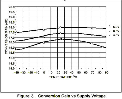
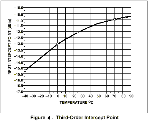
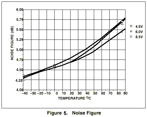
The heart of the receiver is the SA612A is a low-power monolithic
double-balanced mixer with on-board oscillator and voltage
regulator. It is intended for low cost, low power communication
systems with signal frequencies to 500MHz and local oscillator
frequencies as high as 200MHz. The mixer is a “Gilbert
cell” multiplier configuration which provides gain of 14dB
or more at 45MHz. The oscillator is configured for tuned tank
operation. The low power consumption makes the SA612A excellent
for battery operated equipment. Also you'll benefit from very low
radiated energy levels within. The SA612A is capable of receiving
-119dBm signals with a 12dB S/N ratio. Third-order intercept is
typically -15dBm (that’s approximately +5dBm output
intercept because of the RF gain). It also has a temperature
compensated bias network as shown in the equivalent circuit
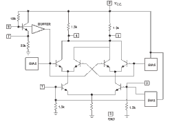
It
works pretty well in this receiver, but in practice it shows some
intermodulation when signals are strong. That is why I added a
bandpass front-end filter. It greatly reduced the
intermodulation.
What kind of radio is it?
You can listen to SSB signals (actually like the SA612 is used
here it demodulates LSB and USB more like a DSB). It does not
separate LSB and USB. CW can also be received as can DSB. AM is
tuned like with any SSB receiver to the dominant frequency peak
meaning the middle of the AM signal (zero-beat). Anyway, because
I wanted to keep the simplicity of the project I opted for direct
conversion. Direct conversion means that you process the incoming
RF signal at its frequency without down converting it to an IF
(Intermediate Frequency) and then processing the IF frequency.
Direct conversion single sideband receivers are of interest
because they are less subject to spurious responses than the
conventional superheterodyne, do not entail the use of high-gain
narrowband amplifiers with high centre frequency, and lend
themselves better to integration in monolithic form.
The most important feature of a direct-conversion SSB transceiver
is that there are no complicated conversions nor image
frequencies to be filtered out. However, the RF section of a
direct-conversion SSB transceiver requires simple LC filters to
attenuate far-away spurious responses like harmonics and
subharmonics.
This direct-conversion SSB transceiver includes some critical
components like precision (1%) resistors en quality capacitors to
ensure its stability. Do not dismiss this, it is important.
Design
tips
To keep the receiver stable as possible and without frequency
drifts you need to use components that has good temperature
qualities. I can not emphasize it enough how important this is!
Using low quality junkbox components will cause a unstable
receiver. I have marked the critical components with an asterisk * .
For * resistors: please use metal film 1%
For * capacitors: please use mika, polystyrene or multilayer ceramic capacitor (multilayer ceramic capacitor has a
many-layered dielectric. These capacitors are small in size, and
have good temperature and frequency characteristics)
Notes: I got it to work by keeping
it small, using very short connections and made the ground
connections large so no RF loops would occur. The dead-bug
methode could probably work too although I did not test it. I
really need somebody who can make a PCB for the RX1HF80!! Anybody
out there?
Anyway, it can be done using a cheap circuit board IF you
take real good care of the connections and ground paths hence
honoring the principles on building (V)HF projects. And keep the
audio stage and HF part separate.
MV2205 Varactor
and tuning
The receiver tunes using a varicap (Capacitance Varactor Diode). If you can not find the MV2205 you can
use a BB409 (*see text
below). Anyway, I could
use the entire very broad 80m band with both types of varicaps.
With other types you probably will need to adjust C17 and C20 and
perhaps R1, or R2, or R3 or R4 or a combination. It will come
down to get a full 80m band coverage and a proper bandspread. We
do not want the entire band in a quarter of a turn from
potentiometer P2. P2 is the main frequency dial and P1 allows
fine tuning.
MV2205: 
BB409 Varactor
I have been experimenting using the popular and easy to find BB409 Varactor Diode. It
has a max capacity of 32pF. Comes close to the MV2205, but the
lowest capacity is a bit more different hence changing a few
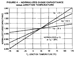
components was necessary. Also the temperature coefficient of the diode capacitance is
slightly inferior, but it causes no problems. It does the job. So
what componenets needs to be changed when using a BB409 instead? You can leave out C17 and
replace C20 with a 220pF component. That's it.
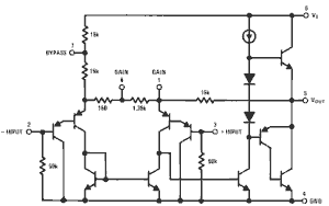
Audio
The audio is power by is a black box LM386 audio amplifier. The
LM386 has enough gain to drive a small speaker and it designed
for use in low voltage consumer applications. Ideal to use in
battery fed applications. The gain is set to the max in this
project and not only by using a capacitor from pin 1 to 8. The
gain will go up to 200 (46 dB) and additional amplification and
audio bandwith range with R7 C32.
Set and
calibrate
To set and calibrate the RX1HF80 we need minimum:
- a 'real' accurate receiver or transceiver that is capable of
receiving 80m SSB
Although most can be done by "ear" It also helps to
have a frequency counter and a RF voltage meter.
First we need to tune the Local Oscillator LO (Colpitts) varactor
tuned tank circuit C19 & L1. This need to be set to 80m band.
With C19 and L1 you can easily tune between 3Mc and 4.5Mc. The SA602/SA612 double-balanced mixer will mix the
incoming RF with LO.
Use a frequency counter or
your receiver/transceiver and place a wire from the antenna
connector in the proximity of the tank circuit. You'll should
hear/see your signal on your radio.
Now we need to peak the front-end tank circuit C9 & L3/L2.
This needs to be tuned for maximum peak/sensitivity on the 80m
band (preferably in the middel of the band). Tuning C9 will
probaly do the trick (in some cases moving the core of L2/L3 can
achieve further tuning if needed).
Specs
Frequency
range: 3000 kHz - 4300 KHz (maximum range with existing components,
not the actual tuning range)
Note:
although the kit can be set to tune anything from 3 to
4.5mc, the design however is made to RX peak in the 80
ham band.
Tuning range: 400kc+/- typ. 3500...3900Mc
Varactor tuning
+/- 1 kc fine tuning (can be set to other ranges, see text)
Modes: USB, LSB, DSB, CW, AM (I was able to decode sstv, rtty and even psk31)
Sensitivity: +/- 0.25uV @ 12dB SINAD
Mixer noise figure typically lower then 6dB
Input impedance: 50 Ohm
AF amp gain 46dB
AF s/n ratio +/- 80dB
AF distortion: 0.5% (AV = 20, VS = 6V, RL = 8W, PO =125mW, f = 1kHz)
Drives a 4...8 Ohm speaker with 500mW output LF power @ 9volts
U = 8...15 volts when external power operated (9v battery works perfectly too)
I = 13mA @ 9volts (digital version only 7mA)
connector for external charging and a connector for LF output (external amp, PC, to decode digimodes as sstv etc.)
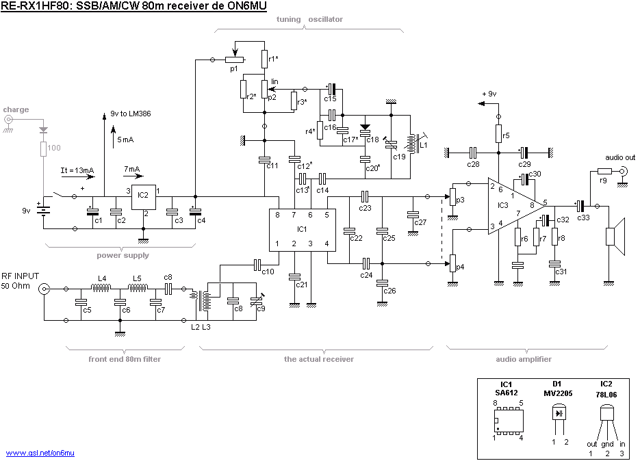
Schematics
Analog version
 |
Digital version
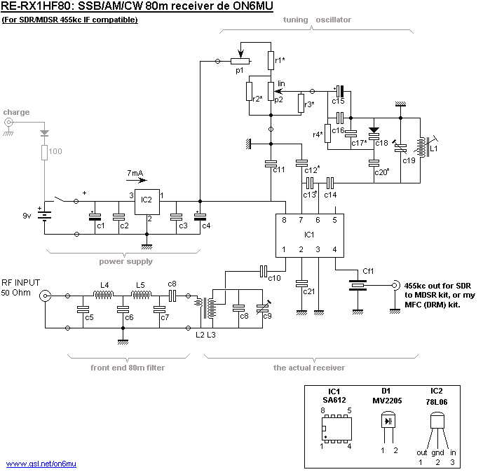
Use the above schematic if you want
to use the receiver with MDSR, or with my MFC/DRM demodulator (or with other 455kc demodulation kits).
The LO needs to set slightly differently then in our analog
version. It needs to be shifted 455kc up. MDSR software is recommended, however it works fine
with other compatible software, like SDRadio, too.
Part list (normal analog version)
|
Details - Coils
L1: 40 turns, 0.2mm litze
(AWG#32), 7mm inside diameter, 13mm long, adjustable ferite core.
Core needs to cover the entire length no longer. (L1 = local oscilator
resonant @ 80m). (Ideal would be to
shield the LO, but this I could not do because of the small pcb I
was forced to use in this prototype)
L2: 3 turns,
0.5mm (AWG#24), 10mm inside diameter (close to the hot side of
the coil, being the top as seen in the schematic)
L3: 30 turns 0.5 (AWG#24),
10mm inside diameter, 17mm long, fits over a ferrite rod (the
core can be 'recycled' from an old transistor radio). A tap @ 10
turns.
Important: both L2 and L3 are on the same ferrite core. L2 is
wound against the hot side of the coil. The tap on L3 is closest
to the hot side. Core needs to cover the entire length no longer.
The
main resonant tank L2/L3 coil is best wound over a bit of thin
cardboard, paper or plastic that snugly fits over the ferrite
rod. The coil can then be slid along the rod to adjust the
maximal sensitivity if needed (in combination with C9). Mostly
the core just covers the entire coil length.
Use this to set the peak the centre frequency the band.
L4 and 5: 35 turns, 0.3mm (AWG#28), 6mm inside diameter, 15mm long. I used a piece of plastic shaft from a potentiometer as "coil holder".
Tips and suggestions:
- use external freq counter to read frequency instead of the
analog scale. (you could
then use a 5 or 10 stroke P2 and leave out the fine tuning P1)
- use a stereo pot (P2) and drive a analog meter to be used as
frequency scale readout. Or even a digital meter! (also here you could then use a 5 or 10
stroke P2 and leave out the fine tuning P1)
- use a RF-gain ciruit (or use a RF dampening circuit: like a 5K
pot that provides gain control by shunting some of the signal to
ground).
- an AGC circuit. Could probably be build around the existing
LM386 and using that amp to reduce AF gain on strong signals, or
an extra amp to function as agc just before the lm386 input....
- when we have found a PCB designer for this project it could
easily be build as a portable receiver (handy) and later on
design a TX circuit...
top view From left to right: Receiver, Filter, Audio |
|
Inside
view 1 |
Inside
view 2 |
Also more of my homebrew projects:
ON6MU Homebrew projects
Radioamateur related projects
ON6MU Ham mods
Modifications of transceivers
..ON6MU
50 Mhz converter/receiver
..Magic band converter
73"
![]()
Home
Radio kits velleman. Radio converter kits.
Kenwood, Yaesu receivers. Electronics schematics of radios.
Building kit of a home made crystal radio with transistor
components. Receiver commercial receiving antenna. shortwave
listening with receivers. Build your own shortwave receiver.
Performance not as a Kenwood or Yaesy receiver but so much more
fun to receive world wide signals. Not using integrated circuits.
Circuits integrated components of electronical contents. Antenna
longwire for shortwave reception.