by OE4WHG
![]() OE - 6m - PAGES
OE - 6m - PAGES ![]()
by OE4WHG
QRV with 10W from 160m to 2m:
The F850 is a so far only little well-known device, which is characterised
however by a number of interesting technical characteristics and might regarding the
combination of the frequency ranges at present be at least unique. The Transceiver covers
all amateur bands from 160m to 10m, additionally the 6m band (50 mc/s) and the 2m band.
The operating modes AM, SSB, CW and FM are possible in all frequency ranges, truly a rare
piece. With this configuration the F850 is interesting for different groups of
users. On the one hand it offers the possibility to newcomers of being QRV
immediately on all bands and in all operating modes with only one device, on the other
hand one the 50-MHz-range can be used as Nachsetzer for UHF converters for the 23-cm-Band.
The possibility for the reception of all types of modulation offers substantial advantages
also here. The large signal firmness of the F850 is thereby a further plus, which is
particularly important for converter operation.
Despite a power output of only 10W the F850 is conceived however as home station with 220V
power supply (operation at 12 V is possible too). Its dimensions and its weight would be
anyway somewhat a hindrance for portable operation. The acquisition of an additional
output stage, which is not suitably offered by the manufacturer unfortunately, cannot be
therefore avoided in the long term if one is not an expressed QRP fan.
The F850 is executed as solid desk housing, in that the different output stages,
which 220-V-Netzteil and the loudspeaker is accommodated. An exhaust is not inserted,
since the large heat sink at the rear side is sufficient to the temperature heat sink. One
looks a band selector and a change over switch up for the operating modes (in the
conventional form as rotary switches) in vain with the F850, because the selection of the
desired area is made by a double-row push button arrangement at the right page of the
front plate. With the two key rows arranged under it the following functions are switched:
VFO: lNT, receipt EXT., transmitting EXT., EXT.
Zf-bandwidth: 0.4 kHz, l,2 kHz, 1.8 kHz, 2.4 kHz (equipped is only the filter for 2.4 kHz)
RF-ATT. 10-dB-Daempfungsglied; Noiseblanker; Calibrator (25 kHz)
Operating modes: CW, USB, LSB, FM, TO
Over further push buttons the RIT and a variable BFO (particularly for W-COperation) can
be switched on and off, additionally they enable the switching of PTT on VOX operation,
alternatively with short or long decay time constant. Also the function of the inserted
measuring instrument, which at FM as focal point display for accurate tuning on the
frequency the remote station operates, as well as field strength or Hf-power output to
display can, over two keys is determined.
The configuration with further controls is limited to the really inevitably necessary
automatic controllers for microphone reinforcement, Hf-hf-Traegerleistung (for CW and FM),
the muting and the Nf-volume. A HF/ZF Verstaerkungsregler is missing.
The frequency display is made by a six-digit LED display, which is arranged over the
large, low-friction co-ordination button directly. The green-lighting up digits are still
very good also during sun exposure to read off.
From the links are arranged the microphone and the jack headset-phone at the front plate;
the three HF HF-Ein / outputs for KW, 50 mc/s and 144 mc/s, inputs for external ALC (of a
linear amplifier) and a key, as well as the output for an external loudspeaker are at the
rear side. Multiple plug connectors are for an external second VFO (as accessories
available), for the operating voltage (220 V or 13.6 V) as well as designated for a linear
output stage.
The receiving element of the F850 is appropriate as single super with Premixer and an intermediate frequency of l2,375 mc/s, the sender operates with two wide-band semiconductor output stages for 1,8 to 50 mc/s and 144... 146 mc/s, in each case with low-passes downstream for each tape. They supply max. 10 W power output.
Fig. 2: HF section of the F850 (sender and recipient)
In receipt position (see fig. 2) the signal coming from the antenna passes through first for each tape an optimized bandpass filter, which on the tapes 2l, 28 and 50 mc/s a common Hf-preamplifier is downstream. A further amplifier is intended for the 2-m-Band. On all other tapes the signal is supplied directly to one from four FETs (two dual FETs) existing quadrature mixer (see circuit in fig. 3). This arrangement ensures on the longer-wave tapes, on which usually on higher field strengths is to be counted and for which disturbing and noise level make a preamplifier dispensable anyway usually, for a high dynamik-Bereich, during on the two upper tapes of KW of area, as well as on 50 mc/s a good sensitivity is achieved.
Fig. 3: Recipient mixer with Zf-preamplifier
To be mentioned it should also that the manufacturer for the switching of the
input filters (and all other filters, quartz etc.), which are used by the way also in the
sender preliminary stages, which selected opposite switches more expensive reed-relays.
This measure is surely along also for the large signal behavior, since switches can cause
additional lntermodulationsverzerrungen with high input field strengths.
The Zf-signal passes through after the mixer first a 16kHz broad crystal filter, which
serves with FM as selection means, afterwards the Zf-preamplifier and by the Noise bright
controlled Austaststufe and arrives finally over a further filter, which can be selected
depending upon operating mode, at the demodulators for FM as well as TO and SSB/CW. The
receipt course is split up for this purpose behind the last intermediate frequency stage
into three branches, which to the FM quartz frequency discriminator (with center display)
and following muting, to the AM demodulator and to the product detector with following
Nf-amplifier to lead. The different AGC time constants are switched automatically with the
selection of the different operating modes. The BFO is crystal-controlled, however its
frequency can be varied over up to + - 2 kHz, which particularly for W-COperation of
advantage is.
The editing of the oszillatorfrequenz takes place via a Premixer, in which the signal is
mixed by 6 switchable quartz oscillators with within the range of 11,95... 11.45 mc/s
tunable VFO (see block diagram in fig. 4). The VFO frequency is digitally displayed, after
a further mixture with the frequency 19.6 to mc/s with the seven-place display on 100
cycles per second. The output signal as double balance mixer executed Premixers passes
through afterwards for each tape a separately structured, two-stage bandpass filter with
an intermediate buffer amplifier, before it is supplied to the receipt or transmission
mixer. The selection of the respective frequency range is made in comfortable way by the
push buttons arranged at the front plate.
Fig. 4: Block diagram of the Premixers
The F850 has 1.5... 50 mc/s and 144... 146 mc/s two Hf-output stages for the
areas. The 6-m-Band can, as previously mentioned, be used for example as Zf-Nachsetzer for
converters or as Exciter for Transverter for the areas 70 cm, 23 cm or l2 cm. On all tapes
the operating modes are FM, SSB, CW and TO possible, however is intended with TO a power
output of only 5 W, during it with SSB, CW and FM max. 10 W amounts to. With FM and CW the
traegerleistung knows by the automatic controller RF-CPower at the front plate as required
zwisehen 1 and 10 W to be adjusted.
The microphone amplifier is equipped with an automatic volume compressor, which is
activated automatically when far untwisting the microphone reinforcement automatic
controller. The respective compression degree can be read off on the polychrome laid out
scale of the multiple indicating instrument.
For the operation over relays in the 2-m-Band the device was equipped additionally
(modification by the importer) with a relay file and a tone call, which can be activated
with operation in the frequency range by 145,5... 146.0 mc/s. Who would like to enter the
frequency range to 148 mc/s, the two necessary quartz can re-tool. The relay file becomes
through printing of the RIT key effective with operation within the indicated area. If one
co-ordinates the F850 then for example with the relay output frequency 145.600 mc/s, the
sender on 145,000 operates. Opening of the relay is possible by operation of the VBFO key,
which activates a tone call.
In addition, the Transceiver is equipped with a 220-V-Netzteil, can be attached in mobile
operation directly to the car battery. Its requirements of electric current amount to with
receipt 1.5 A and rise when transmitting to 3,5 A.
In the practical operation the F850 showed an excellent sensitivity (intoxication corridor - 132 dBm on 14 mc/s, -134 to 50 mc/s) on all tapes, as well as a very good large signal behavior, which might be FET FET-Quadraturmi to attribute particularly to the used and which made Hf-Daempfungsglied almost unnecessary in practice. During the erprobungszeit no lntermodulationsstoerungen could be recognized. On the other hand one misses a Hf or a Zf-Verstaerkungsregler, in order to be able to reduce with sufficiently high field strength the remote station the reinforcement in such a way that in the sprechpausen the QRM does not come through so strongly. This effect is strengthened still by the relatively short decay time constant of the AGC, so that the otherwise good receipt quality suffered somewhat from it. At least the extension of the decay time constant should be also subsequently realizable, so that an improvement borrowed itself in this way cause lets. The operation of the device proved as completely unproblematic, since one got accustomed to the push buttons designated for switching rapidly. For W-COperation the inserted SSB filter is too broad, so that one should to absolutely be able to be inserted an addition filter.
. Sensitivity: 80m: 0,19µV, 40m: 0,28µV, 20m:
0,12µV, 15m: 0.12µV, 10m: 0,12µV, 6m: 0,1µV, 2m: 0,15µV
. Automatic gain control: Between 100 mVs and 0.8 µV input voltage
resulted a decrease of the Nf-signal of -6 dB (approx. 100 dB AGC aGC-Dynamikbereich)
. Noise floor: 14 mc/s: -132 dBm; 21 mc/s: -134 dBm
. Dynamic range, free of intermodulation: 90 dBm (two signals with a
level of in each case -42 dBm and 20 kHz distance cause intermodulation products, 3 dB
over the noise is situated.)
. Hf. power output: 80m:12W, 40m:12,5W, 20m:13,5W, 15m:13,5W, 10m:14W,
2m:13W
. Frequency ranges: 1.5... 2 mc/s, 3.5... 4.0 mc/s,
7... 7.5 mc/s, 14... 14.5 mc/s, 21... 21.5 mc/s, 28... 30 mc/s, 50.. 54 mc/s, 144... 146
mc/s. Only receipt: 14.5... 15 mc/s (WWV)
. Operating modes: SSB (USB/LSB), CW, TO, FM
. Power output: SSB/CW = 10 W, TO = 5 W. with FM/CW adjustably
. Carrier suppression: better than 40 dB
. Sideband suppression: better than 40 dB with 1000 cycles per second
. Countershaft suppression: Minimum 50 dB within the area 1.8 mc/s to 28
mc/s, 60 dB between 50 and 144 mc/s
. Harmonic wave suppression: better than 60 dB for the tapes 1,8.. 28
mc/s, over 70 dB over it
. Stability of frequency: better than 100 cycles per second within 30
minutes
. Sensitivity: 1.8... 14 mc/s: 0.3 µV for 10 dB S/N; 21... 146 mc/s:
0,2µV S/N
. Selectivity: FM: 16 kHz; SSB/AM/CW. 2.4 kHz; with addition filters: 1.8
kHz, 1.2 kHz, 0.4 kHz.
One uses 0.4 kHz filters for CW, an additional reinforcement level provides for a balance
of the signal level, so that practically constant signal-strength meter display results.
. Af. Ausgangsleistung: 2.5 W
. Dimensions: Width 36 cm, height of 16 cm, depth 36 cm; Weight: 13.5 kg
. Standard price: approx. DM 2.600, - with power pack
. Importer: Walter J. Schorr KG, 6000 Frankfurt/Main, Albusstrasse 18
beam 2/81
SPECIAL PRODUCT REPORT
SUGIYAMA F 850 HF/VHF TRANCEIVER
(Practical Wireless, September 1980)
The first impression (having recovered from lifting the set from its packing!) was of a superbly engineered piece of equipment, not flashy, but very professional. This was confirmed by the feel of the controls and switches, even before power was applied, and also by the internal construction, with one minor reservation, but more of that anon.
The need for the review set to be returned for an exhibition appearance meant that we did not have time to carry out the sort of measurements that we normally perform on h.f.-band rigs, and the views here are the result of a couple of weeks of testing on the air.
Features Perhaps the best way to give a run-down on the operating features is to describe the function of each control and connector. Starting at the top left-hand corner of the front panel, we find a large illuminated meter, controlled by two pushbutton switches. This indicates r.f. power output or the compression level of the speech processor when on transmit, and received signal strength or f.m. tuning point (centre zero) on receive. The 5-digit frequency display is bright, and stable in the last digit (100Hz) and indicates true transmit and receive frequencies, including any shifts.Band switching is by push-button, and is arranged in 500kHz sections. To reduce the number of push-buttons required for band switching, two banks of eight are provided, one covering the eight bands, the other the eight 500kHz-wide sub-bands. In the UK model, only the lower four subbands are used, but in export models for Regions 2 and 3, a 4 MHz spread is required on the 6-metre (fitted in place of the UK 4-metre band) and 2-metre bands. An invalid selection of bands or sub-bands will cause the frequency display to flash, alerting the operator to his error.
Below the band and sub-band switches, is another bank of 16 buttons. Four of these allow the transmit and receive frequencies to be controlled from the internal v.f.o. or an external source, as desired. A further four buttons select the receive i.f. bandwidth on c.w., a.m. and s.s.b. Only the 2.4 kHz filter is fitted as standard, the remainder being optional extras. The bandwidth on f.m. is fixed at 16 kHz.
The lowest row of buttons control a 10dB r.f. attenuator, a noise blanker, a 25kHz crystal calibrator and select the mode: c.w., u.s.b., l.s.b., a.m. and f.m.
At the bottom right-hand corner of the front panel are the receiver incremental tune (±5kHz and variable b.f.o. (±2kHz) controls, each with its on/off selector button and warning l.e.d. indicator. When on 2m f.m., these pushbuttons instead select repeater shift and automatic 1750Hz toneburst respectively, though there is no indication of this on the front panel markings.
The main tuning control is a heavy flywheel knob, approximately 55mm in diameter, with a finger-dimple for rapid winding, and placed well clear of all other controls. The tuning rate is about 16kHz per revolution. Like all the rotary controls on this set, the operation is silky smooth.
To the left of the main tuning are four knobs: the microphone gain control, setting speech level and compression; the r.f. power control, allowing the output to be varied between 1W and 10W (nominal) on f.m. and c.w.; the squelch control (f.m. only) which is of the "gradual" type, rather than the "step" type, and so is precisely settable, rather than having hysteresis; the receive volume control (a.f.. gain). A large push-button switch turns the power on and off, and three smaller ones connect the p.t.t. lines and select "fast" or "slow" VOX time constants. Normally, "fast" would be used for c.w. (the Morse key controls a tone oscillator, which provides sideltone and keys the transmitter via the VOX), and "slow" would be used for speech. Connectors for headphones (4-8Ohm, and 600Ohm microphone with p.t.t. complete the front panel features.
On the rear panel are three sockets, all SO-239 u.h.f. type, for h.f., 4m and 2m aerials, plus connectors for external v.f.o., linear amplifier, p.t.t., key, extension loudspeaker (4-8Ohm) and power. Two power leads are provided, one for a.c. mains, the other for 13.5V d.c. M or /P operation, and both fitting the same connector.
Practical Wireless, September 1980
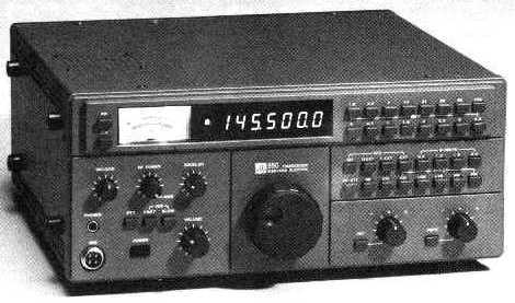
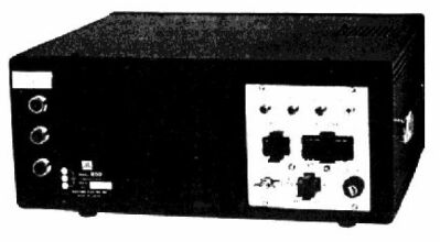
Front panel view of the F850
showing the various controls and indicators.
The frequency is displayed as a digital readout with an analogue S meter to its left
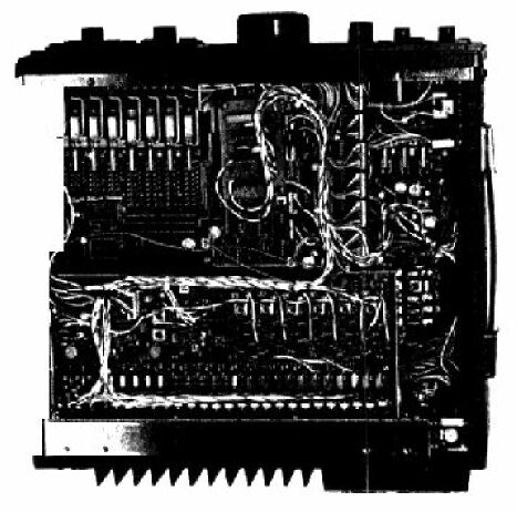
Bottom view of the transceiver gives some indication of the excellent workmanship as well as the complexity of the rig
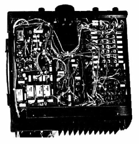
This top view shows the complexity of the switching arrangements together with the many crystals needed to cover the bands
As well as acting as the main heat sink for the unit the rear panel also carries the various aerial sockets and the power inlets
Operating Impressions
Contacts were made on all bands except 70MHz, and all modes, over a period of about two weeks in March this year. No stations were heard on 70MHz, though on an admittedly makeshift aerial. Contacts on c.w. with W/VE-land on 20m, 15m and 10m, all brought reports of around the S4-S6 mark, which can't be bad for a set pushing out a measured 12-14W via a Z-match into a 60ft long wire. Similar results were obtained on 80m and 40m, with European stations.Phone contacts around the UK brought reports of really excellent speech quality on 80m and Top Band, the latter using a large "T" aerial at a different OTH, as the long wire refuses to tune at those frequencies.
On 2m f.m., a rather poorly sited "Slim Jim" brought an S9 report from a handheld, operating indoors, about five miles away on the other side of a hill. Other contacts around the district seemed to produce similarly respectable results. A quick test on 2m s.s.b. using an 8-element Yagi at a different QTH seemed to suggest that receive sensitivity was somewhat down, by comparison with another rig.
Apart from this, the receiver side performed superbly, the very low rate of the main tuning making s.s.b. operation a joy. The r.i.t. rate was, as on almost all sets looked at recently, greater than desirable, or indeed necessary. As to the switchable bandwidth facility, the basic 2.4kHz performed well on s.s.b. and a.m., whilst 1 .2kHz was good for c.w. searching, and 0.4kHz excellent for winkling out c.w. from the QRM. The 1.8kHz filter did not seem to fill any particular need. The audio output quality was reasonable, but suffered from being emitted from an upward-facing loudspeaker. An external speaker was not tried.
The operating manual supplied with the set very definitely did not match up to its quality, being a duplicated typewritten document just 13 pages long. No technical description of any sort was included, though there was a circuit diagram on a loose sheet. This had obviously been reduced from a very much larger original, and would require either extremely good eyesight or a magnifying glass to be of much practical use. The operating instructions given were quite comprehensive. We understand that a better manual is in preparation.
I mentioned earlier one reservation on the internal construction, and this was regarding the linkage between some of the push-buttons and their switches. However, the remainder of the set gives such an impression of being designed and built by people who know exactly what they are about, that I'm prepared to give them the benefit of the doubt on this point. Certainly, I had no problems during the tests, and the importers say they have had none either.
So there we are. The F850 is a bit weighty, and rather low in power, though the importers, Zycomm, do offer a suitable 220W linear for the h.f. bands at around £80 including VAT. On a value-for-money basis, it seems pretty competitive with an assemblage of sets and converters to provide the same facilities, though it does sound a lot of money for a 10W transceiver at first sight. There is, I suppose, the "eggs in one basket" aspect as well. Finding a spot for mobile installation will prove a problem in most cars.
Specifications Frequency coverage: 1.5-2.0MHz, 3.5-4.0MHz, 7.0-7.5MHz, 14.0-14.5MHz (extended to 15MHz on receive only), 21.0-21.5MHz, 28-30MHz, 70-71MHz, 144-146MHzPractical Wireless, September 1980
Block Diagram of the F850
Circuit diagrams in four parts (bad copies, who has better ones?): #1, #2, #3, #4
Bedienungsanleitung (User Manual, german
only)
Back to: OE 6m Pages