Ever
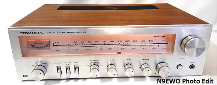
wonder where the serious rich deep "Bass" frequency response went
with newer
Stereo Receivers ? Sadly when the surround sound "home theater"
craze
hit in the late 80's so did the full range "Music" Class AB amplifiers
used in receivers. In
order to cut manufacturing cost, the use of Class D amplifiers designs
were (and still are) put in play. These amplifier designs have a higher
distortion level, and require a much lighter power transformer (for
reduced costs). This trend started to take hold as early as the mid
80's and by 1990 was the industry normal by all manufactures. The low end Bass response GREATLY suffered
if not
made non
existent on purpose. Here all manufactures said for low end response to
make use
of those excessive (overkill) and high distortion sub-woofers. Of
course using any sub-woofer is NOT suitable for listening to "Music"
(at least in my book it's NOT).
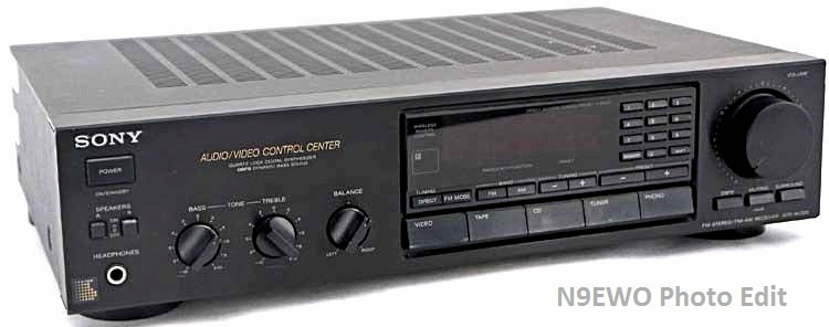
Now these
days even the "Loudness" button has disappeared. This helped to
restore the "Bass" response at lower listening levels. So for
listening to "Music" these Class D amplifier receivers are all totally
worthless. You might say......"well I
will just use a external EQ to recover
the lost low end"
? You would think that would fix that , however these
Class D amplifiers are NOT made to produce the rich low end Bass
response ,
so the owner will probably destroy the amplifiers electronics in time
as it struggles to produce some "low end" and if it does at all (if not
the
damaging the connected speakers with it) ??
Going back a bit in stereo amplifier history, around 1979 there was
a push by a
number of Japanese manufactures using a tricky way of reducing
amplifier distortion using Class B efficiency with the highly preferred
Class A linearity. This is done by dynamically varying the bias voltage
of
the output stages (no.....it's still not a true "Class A" Amplifier).
Sony called this "Spontaneous Twin Drive", Hitachi :
"Super Linear", Technics (Panasonic) : "New Class A" , among others.
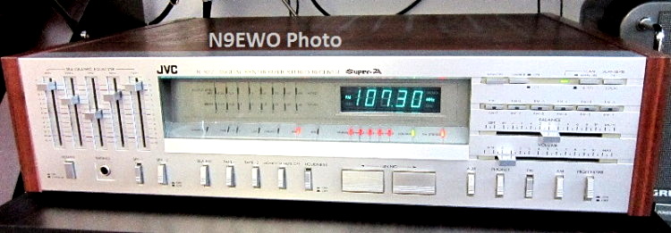
JVC
used the name "Super A" and in late 1980 the R-S77 was the first
"Digital Tuner" receiver
in their lineup to make use of this circuit. It put the Total Harmonic
Distortion (THD)
at a creepy 0.005 % (with 60 watts per channel).
Mind you many "so called" audio
experts discount this "Super A" scheme saying it makes the amplifier
musically incorrect. I must say I find this to be "total rubbish" as
least with the JVC R-S77
covered here. We have owned a number of NEW
Stereo
Receivers (no...not separates or high end) of the late 70's into the
2000's and must say it's one of the best stereo receivers my ears have
ever
experienced (if not the best) . Not the perfect situation mind you, but
is better with the "Super A"
than without. It's extremely clean and full sounding to OUR ears.
JVC refined this with the "Dynamic Super A" design around
1985. Was
advertised for improved dynamic range over just Super A. The first JVC
models to offer the "Dynamic Super A - GM Circuit" was the R-X500 ,
R-X400 and the R-X300 and were not reliable receivers with the
first try on the new circuits. Widely known
for amplifier failures with only light use from excessive heat stress
(also first hand friends experiences of the R-X500 model).
But after owning a bit
later improved RX-8V
receiver with this circuit we feel the rich Bass sound was not so
great anymore (but it was still much better than later models after).
It
also used true Class A preamp's which still made for a very
HOT running amplifier and prone to failure (more later on this).
The
R-S77 has this
desirable DEEP BASS, and with it's built in "wide range" 5 band EQ
makes for a perfect mix with the right speakers. OK this is an
IMPORTANT part of this of course (common sense) : One of course MUST
use
large enough "decent" speakers to experience this Deep Bass" trait. We
use a pair of modern low cost but still excellent (now discontinued) "Pioneer S-H253B-K" 3 way "8 inch
woofer" speakers that have a bit above average bass response.
These
speakers still do not have the "Classic Bass" sound with ANY Class D
amplifier receiver
we have tried, but are excellent with the JVC R-S77.
Note: Even JVC's "Dynamic Super A"
surround sound receivers made in the 1990's and beyond also suffered
worse from the lack
of rich low end. I do know from friends
personal experiences that JVC's amplifier reliability was even worse of
a
problem in this era and even right to the end as they generally also
ran super hot even at idle.
So for the JVC R-S77
The JVC R-S77 Super A "Synthesizer Stereo Receiver" was released in
late 1980 for a MSRP of $ 560. in the USA. It was the top of the JVC
line
receiver at the time. I remember purchasing my first one in early 1981
for about $ 500. street price. These were in great demand at that time
and I had
to be put on a waiting list at the local dealer. Took about a month to
be able to fork down the big $$'s to obtain one. Made the BIG mistake
of upgrading to the R-X60 a few years later (which was actually a
huge downgrade as we cover below), and made even BIGGER mistake letting
the
R-S77 go. Of course making the purchase of TWO used ones a few decades
later
as used for this report.
Size of the R-S77 is around a large 4 5/8 x 18 3/4 x 15
inches and
the
weight is 23.8 pounds (10.8 kg). Yes its size was a bit odd and large
even today.
It's front panel is made of (fairly) thick "sliver" brushed aluminum.
The wood colored painted metal shell and pressed wood
side panels only existed with North American versions. In Europe and
Asia it was sold in a "all silver" cabinet minus any wood side panels
(so was a tad less of a beast and weight). Beautiful anodized THICK
steel undercarriage and it's 2 trap doors for access for bottom access
for the amplifier and tuner PC boards. Audio power output rated at 60
watts per channel. 2 real tape monitors (inputs and outputs) along with
one "Aux" line level input. We cannot forget the "BIG" feature of a
built in 5 Band Graphic Equalizer (what JVC called "SEA"), with the
nice + and - 12 db range.
FM "Synthesized" tuner section features a
FET front end (MOSFET mixer) and a 5 LED signal strength meter. The old
school green "Locked"
LED comes in handy for indicating if any given station is on frequency.
I found the FM tuner is sensitive to impedance, so
to achieve it's great sensitivity one must use the right antenna and
feed line even with indoor antennas. There is a 75 ohm connection but
is not via a F connector (binding post and a clamp). No dial strings to
have to worry
about breaking of course as it has none. I'm spoiled now, so no more
analog tuning for me anyway. Sorry, our tests did not include any
testing of the AM (MW) section.
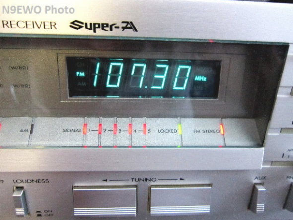
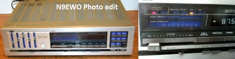
JVC's R-S77 with
it's custom Fujitsu florescent display.
FM tuning steps can be set to 50 kHz even with the USA version
(socket/plug
change on Synthesizer board).
However this will makes MW band only to work at 9 kHz steps. (N9EWO
Photo)
We
have 6 memory presets (6 for FM and 6 for MW) that work well with a
nice large florescent
display that features a very much needed 2 step dimmer button. Bright
is way too intense for our eyes and location. It's large Fujitsu
florescent displays have seem to have
held
up well over the years (your situation could vary). Neat part of the
synthesizer tuner (and anywhere else in the receiver) is there are no
noisy "problem prone" switching DC to
DC converters in the R-S77 for the florescent display. You sure don't
see that anymore. These days that is a cheap way out to provide other
operational voltages at the cost of added circuit noise.
Undocumented tip :
If one moves a jumper on the right side of the tuner synthesizer board
to it's other socket on North American versions (only do when off of
course), one can tune in finer 50
kHz steps on FM. However here the MW-AM band is forced at 9 kHz steps
only. It will
also tune down lower to 87.5 MHz (only 87.9 MHz and 200 kHz steps in
the USA position). We can't forget one other feature JVC included on
many of it's stereo receivers in this era, the neat dual 16 Green LED
power
meters. It also runs generally COOL. Only a tad of excessive heat from
a power supply
regulator transistor and that is it.
Excellent ergonomics, layout of all mechanical type buttons and
controls is superb. There
are no noisy microprocessors lurking about in this receiver either.
However
as JVC did in the late 70 and into the mid 80's, they loved that "No
Knob" design on stereo receivers and made use of "slider" controls. Of
course the R-S77 has just that for
it's Volume and Balance controls. These have a L-O-N-G travel area and
work adequately including equal left and right levels in adjustment
(also are very well made). These (and the 5 EQ sliders) needed to be
PROPERLY cleaned and lubricated during restoration and more on that
subject next.
You might ask, does it have a remote control ?? You have to remember
the R-S77 was designed in 1979 or....so NO of course it does not.
WARNING : I will NOT be held
responsible for any information that is listed here.
ALL
DONE AT YOUR OWN RISK ! |
Sample 2 Was Not Working As Received / What
To Do
(only IF you dare, this is for folks who have some Electronic Experience) ??
Alas the acquired "number two" R-S77 used sample was not working right
when
received. The left channel was
indifferent (that is was flat sounding) aside from very intermittent
output. Dirty switches and controls
were of course part of the problem here (and can be expected being as
old it is).
However
the main and very common bug in it's old age of this model are the
solder connections
with the EQ pots to it's PC board can go sour. For sure as soon as we
ever
so lightly touched the EQ PC board, it came back to life. So we needed
to remove this
board and re-solder all of these slider pot control connections. Mind
you the
electronics were all good in this sample (...whew !). For any sample that
has been
abused in it's lifetime it could very well need more TLC and parts (if
available). I have seen comments around the internet that it's
LONG "ON-OFF" power switch can become nonoperational in these with age,
and that is a weird custom part with a second switch on the end (no
problems experienced with both test samples).
Important note on what to use to PROPERLY clean the switches and
slider controls :
For all of the mechanical switches we used Caig D-5 Deoxit (spray can
type). Only way we found to get spray into these switches was
from the
front, so
it was a MUST to remove the front METAL Bezel. It only has 5 screws,
in fact the entire R-S77 is easy to work on. We needed to do this
anyway
for removal and service of the EQ board. You will have to carefully
remove the small pre-amp board which sits in front of the EQ board that
also plugs into it, plus the headphone jack to get it out. The EQ board
has 6 total screws holding it in. It was a bit daunting to get it back
in place but with a bit of patience was not a problem.
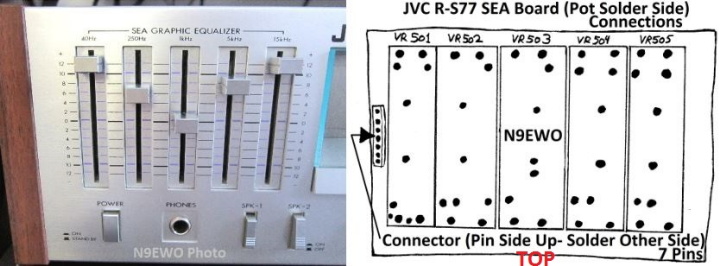
A common issue
with the R-S77 are bad solder joints on the SEA "EQ" PC Board.
Our crude drawing
on Right shows what needs to be touched up (including the socket pins)
Photo on Left show
our normal use EQ settings. See text for more details. (N9EWO
Photo)
When one PROPERLY uses the D-5 for cleaning of the mechanical
switches
(not so easy to do as you should use the high setting on the spray can
to be
sure it gets in there via it's very small openings) , expect
considerable over spray. So just let it run out of the bottom and in
a few hours will dry away (be sure and work these switches well right
after
spraying). We cleaned up the leftover-overspray in the main clean up
later. IMPORTANT : We did NOT (and was not required) clean any of
the upper right and tuner memory buttons/switches nor the up and down
TAC tuner buttons.
FYI : Service Manual for the JVC R-S77
can be downloaded on the
excellent "Hi-Fi Engine" web site here (registration is
required, but
is free).
Important : One does NOT want to
use Caig
D-5 in
ANY of the slider pots. It
contains a solvent and will wash away the virgin lubricant (dry it out)
and will lead to failure of the control. Caig "Fader
Lube F5" (spray
can version is fine but also comes in a less messy but more pricey
liquid bottle version) is what you want to use here. If you must have
that slightly restricted feel of the slider, Caig also sells
"Fader
Grease" (used after Fader Lube). But don't use too much of it
and
is a bit on the pricey side too.
As an alternative to the "Fader Lube", one can make do using Deoxit D100L
as well (as suggested by Caig).
This version of Deoxit has no solvent
and has additional lubricant. This is what we did and worked great.
Instead
of spraying, we used a flattened Q-Tip and applied it right onto the
slider pot tracks (much less clean up of course). Also see the links at
the bottom of this review for additional information on this.
When doing the main cleanup, be sure and clean the headphone jack.
With
the test sample it was near non operational being extremely DIRTY.
Appears it was never used
in it's life before (until me) ? Take note it's ground connection is
made via the mounting hole and nut of the jack (clean around it as
well). Also be
sure and make sure all PC board screws are tight (these can shrink with
age and bad grounds), properly clean the main output
speaker relay (it's the only relay in it), and also check and PROPERLY
adjust
the idle bias current on both channels via the service manual
instructions. It is bound to be off a bit after so many years. WARNING :
As it goes with ANY vintage receiver or electronics in general,
electrolytic capacitors are always prone for failure with age. When in
doubt,
change them out !!
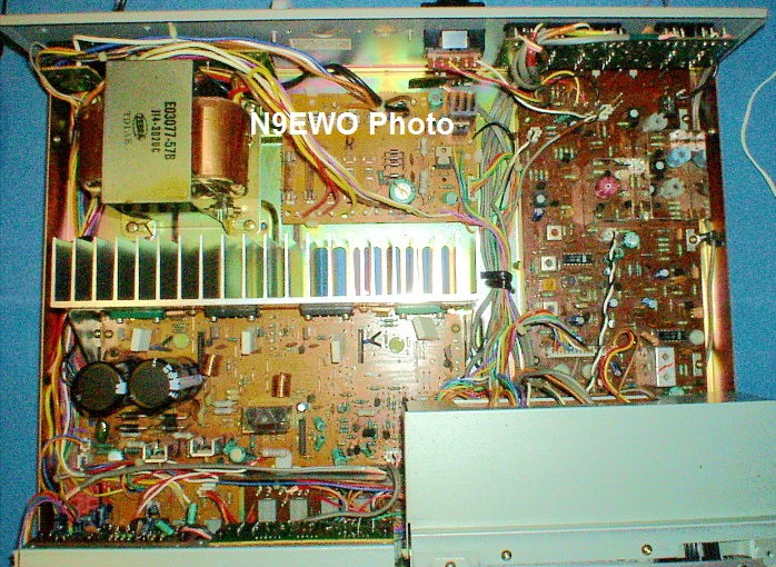
Internal Photo of the JVC R-S77 "Synthesized Stereo Receiver" (after a good clean up)
Tuner Synthesizer Board is located under the metal cover in the lower Right (as shown on photo above). (N9EWO Photo)
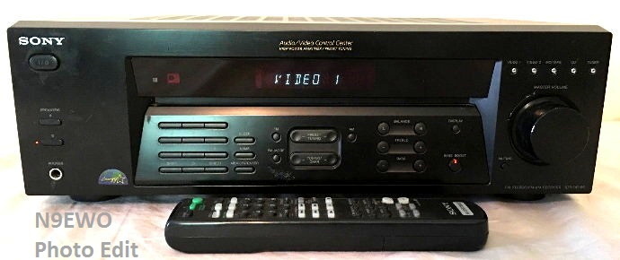
A Very Bad Decision : The JVC R-X60
JVC's R-X60 Stereo
Receiver from around 1983 with it's unacceptable "Slider Volume"
control.
Is extremely stiff
and near impossible for any FINE adjustments. Quality is nothing like
the R-S77's slider controls !!
Also quality of engineering took a back seat as it did for many
manufactures in this era. It was still "Made in Japan".
In around 1983 the JVC R-X line appeared on the market (R-X40, R-X44
{later},
R-X60 and the R-X80). All looked very pretty and I purchased a R-X60
model for an expected upgrade (shown above). This was a very BAD
decision and turned out to be
severe downgrade. It sounded good enough (but yes it was lacking a bit
of the R-S77's deep bass I will admit) and decent FM tuner with a
pretty STEREO
icon in the smaller florescent display.
But the real severe problem with the JVC
"R-X60" (and all models in this series) was
with the much lower quality
slide volume control. Not only was the
travel area much shorter and extremely STIFF, the extremely long shaft
made for near
impossible fine adjustment. To make matters even worse the Left and
Right channels were off, so one was forced to fiddle with the Balance
control to offset that. This difference varied as one turned it up as
well (so constant fiddling with the balance control). It became
very frustrating in short order
!! The top of the line R-X80 used a motor assisted volume control and
hopefully was not an issue here (model not tested) ?
The general quality of construction that the R-S77 had all but gone
too. Thick metal chassis was a thing of the past, also what was up with
that idea of the cheap plastic cover on the headphone jack ?? The JVC
magic was fading into the sunset fast with these slightly later models
in our view and
it never returned again even with the more decent RX-8V a few years
later !!
JVC RX-8V "Dynamic Super A"
Just before we grabbed two used R-S77's, we acquired a nice condition JVC
RX-8V model in the early 2000's.
This advanced featured receiver boasted 3
microprocessors and the later
"Dynamic Super A" amplifier (with the GM
circuit). It sounds much better over ANY Class
D stuff , however the amplifier SUPER DEEP Bass response are somewhat
restricted when
compared
to the R-S77 (but not by much). The 7 band EQ is all electronic
adjustments with memories
and "Spectrum Display". Is very nice,
but still lacks the lower range of the older model as the EQ range is
only + -
10 db range
instead of + - 12 on the R-S77 (could this be some of the reason why
??).
However the vertical "Class A" pre-amplifier board runs quite hot. Uses
3 of those fuse bulbs in
sockets to light up the 3 LCD's (12 volt bulbs). The slider volume
control was gone by this era, again using electronic adjustments just
as with the EQ settings.
The stellar performance item with the RX-8V's is it's FM tuner section.
It has one of
the BEST (if not the best) performing FM tuners we have EVER
encountered within a stereo
receiver. QSC circuit or not with EXCELLENT sensitivity /
selectivity and extremely low noise. It has a MPX blend / quieting
circuit
that is engaged automatically on weak signals, called QSC or "quieting
slope circuit". It works extremely well to eliminate noise on weak
stations and without reducing sound quality at all.
Downside is it also suffers from a tuner bug that
plagues
most of these series models by now (RX-5, RX-7, RX-8, RX-9). The cheap
plastic murata trimmer capacitors fail (just like with the JRC
NRD-545
Communications Receiver). So we had to replace these 2 to 10 pf value
(5 of them : TC
101,102,103,104,105) with
high quality ceramic ones and then do a total realignment. Service
manual for
similar RX-9 we found on the
excellent Hi-Fi engine web site, the RX-8 uses
the same tuner board. Once the
repair was done it was a huge surprise on it's superb FM performance.
JVC used
a rats nests if ribbon cables attached with some ill conceived sockets
in this receiver (as JVC did with many models these days). These
connections are
also
notorious for being problematic and should all be checked for proper
contacts. The older R-S77 uses none of these ribbon cable sockets.
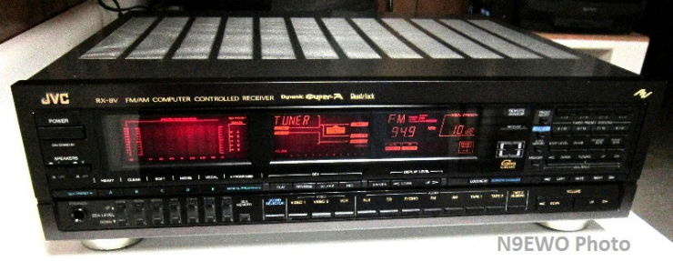
JVC RX-8V
"Computer Controlled Stereo Receiver" from 1986~1987. Dynamic
Super A
amplifier (with GM circuit).
A MUCH IMPROVED
version
of the earlier 1985 "R-X500" dreaded model that was a totally unreliable
beast. Worked
well for the Bass Response. However it's
extremely HOT operation
(even at idle) can lead to pre-amplifier
failures if proper ventilation is not provided. Trimmer capacitors in the Tuner Section are a well known failure issue
with the RX-8V and others in this series (see text above). (N9EWO
Photo)
Final Word : The JVC R-S77 is Worth
Restoring for
Very Nice "MUSIC" Stereo Receiver (if you can locate one in good
condition)
If you appreciate listening to music that contains the rich "bass"
sound you remember from decades ago (with the right speakers) the JVC R-S77
is a excellent
choice plus the modern side of a nice digital tuner / memory presets
with a generally cool operating amplifier. As long as ALL the
electronics work properly and has not been
severely abused, we feel the JVC R-S77 Stereo Receiver is an excellent candidate for
restoration even in it's old age. JVC made quite a number of these in
it's early 80's production, so used ones are still fairly easy to
obtain. As with all used / vintage electronics, condition and operation
can vary
greatly when one finds one. I have seen some samples that look to have
been thrown off a
NUMBER of cliffs. So hunt carefully....enjoy !
Dave N9EWO
©
N9EWO, all rights reserved
Ver 4.0
Links /
References (all Subject To Change
Without Notice)
"Classic Receiver's" - R-S77 Review (May 2020)
Hi-Fi Engine (Great Source for
Manuals)
How can 30-year-old
stereo receivers sound better than new ones ?
Receiver Shoot-Out:
Vintage vs. High-Tech
"Audio
Power Amplifier Design" by Douglas Self , 5th Edition 2013 (JVC Section)
When
do I use DeoxIT FaderLube?
Vintage
Audio System Maintenance
JVC
Dynamic Super-A and Gm Circuits
N9EWO
Review :
C.Crane "FM REFLECT"
Indoor FM Antenna |
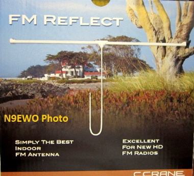
C.Crane's
"FM REFLECT" Indoor FM Wall Antenna (it's outer box photo above).
100% Passive and
Respectable. Made in China. (sorry no longer available new) (N9EWO
Photo)
PRO
:
Improves FM Broadcast reception over the standard T-style dipole that
was included with older Stereo receivers. Passive design for excellent
signal to noise ratio. Design is much less affected by people
moving around in the room (a major issue with any indoor antenna). 8
foot 75 ohm coax feedline (no 300 ohm twin lead feeds lines used here).
Mounting ears and center section that have nail mounting holes
(required to use, see con). All white color. Includes a 75 to 300 ohm
transformer.
CON : Wall mounted antenna,
generally ugly and difficult to hide, must be mounted to something and
is not easy to deal with with it's thick elements. Stiff coax cable.
Pricey for what it is (at full price). Heat shrink piece over coax
connector was not
done properly and made for difficult connection to receiver (one can
just carefully remove it with a pair of scissors). As it is with any
indoor antenna some experimentation may be required to locate the best
hot spot in the room (may require an extension of the coax cable). The
weird whip portable antenna connection with the provided 75 to 300 ohm
balun and alligator clip
did NOT provide any improvement in our testing (we say any host
receiver MUST have an actual antenna and ground connection, 75 or 300
ohm).
Final Word : This 54 inch
"INDOOR" FM broadcast antenna was a winner in our tests. After trying
many indoor FM antenna's over the years, this one works and no fiddling
with some phasing control. We tested this in a horizontal configuration
(see photo below). Not that it will make the weak station jump to full
scale signals (it can't and doesn't). But when directly compared to a
dipole antenna that were included with older stereo receivers from
years past (not a folded dipole type), the C.Crane FM REFLECT was
definitely an improvement (on a some stations it was quite surprising).
Completely passive design, this is NOT another and undesirable active
antenna either (designs which we don't bother with anymore at all), so
NO added noise to the signal. We
found it worked equally well across the entire FM broadcast band (88 to
108 MHz). A bit ugly yes, but is still easier to hide over a even more
ugly pair of "Rabbit Ears".
Sadly this antenna has been discontinued and no longer available new.
Dave
N9EWO
© N9EWO, all
rights reserved
ver 2.1
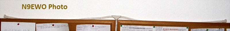
The C.Crane
"FM Reflect" is a bit on the unwieldy side and is less stiff than one
would hope for. We mounted the test sample on the top of 2 bulletin
boards with it's feedline coax neatly hidden in the space between them.
There are TINY mounting holes at each end and a couple in the middle,
but to use these will take a fairy long and thin nail etc. Being as
"thugly" as it is, it cannot be used without some mounting support
(must be wall mounted). In testing it would have been nice to have seen
the coax slightly longer than it's 8 feet (say 10 to 12). But is easily
lengthened (the shorter the better of course.) (N9EWO Photo)