Sequencer for 70MHz Transverter
I have been running a UT5JCW transverter using an IF of 28MHz at ~100mW from my HF radio. I recently changed HF radios and the minimum output is now 5W (without at least more tinkering than I'm currently willing to do). On the face of it, this seemed fine as I was also using the UT5JCW 30dB attenuator board, so that IF drive was still well below the maximum of the transverter. However, the attenuator board is (clearly) not used on RX. So making sure the transverter switches to transmit (hence the attenuator in place) before the IF radio transmits its 5W is rather important. If I do not get the order right I put 5W into the transverter RX path, which doesn't seem like a good idea.
My original "solution" was to switch the transverter to TX manually with a switch in my right hand, whilst I held the fist mic and PTT in the left. Remembering "transmit: left hand first", "stop transmit: right hand first", is difficult in the heat of a contest. So I wanted some way to sequence the IF and the transverter.
Sequencer Ideas:
Both IF and transverter need to be switched from a single master PTT, which sends individual switch-to-TX signals to both the IF and transverter separately and crucially in the right order. One idea was to use a diode and resistor in parallel on the gate of a MOSFET, and use the gate capacitance to act as a timer to "charge up" the gate. The diode causes quick discharge. If the other MOSFET had the same time constant and the opposite polarity diode, then one MOSFET would switch 'on' quick and 'off' slowly and the other vice versa.
As always there's probably a 555 timer circuit solution, but I didn't look into it, opting straight for the sledgehammer-to-crack-a-nut solution of an Arduino Nano. This allows precise control over which MOSFET switches when, and allows signaling LEDs to show what the Arduino thinks should be happening. I opted for a "heartbeat" (that is, pulsing) "power on" light, which it helpful in showing that the Arduino is awake and has not crashed. Finally the Arduino allows for a serial interface for debugging or at a later date, computer control of TX and RX.
Many HF radios have an external PTT input socket on the back, but mine didn't. Whilst it did have an external PTT-out that is not a lot of use. By the time the PTT on the back of the IF goes low to tell the transverter to switch to TX, the IF is also sending 5W up to the transverter. The inelegant solution to this was that I had to switch the IF radio to TX via the 8-pin microphone socket on the front.
Version 1:
an unboxed version tested on the bench highlighted two problems during the October 70MHz UKAC. The first problem was that my conservative 100ms delay on switching meant that I lost the first letter of everyone's call-signs - easily fixed. The second problem is that RF was getting into the microphone. Hence the addition of RFCs on the inputs, and a pause whilst I await delivery of screened microphone cables and a metal case.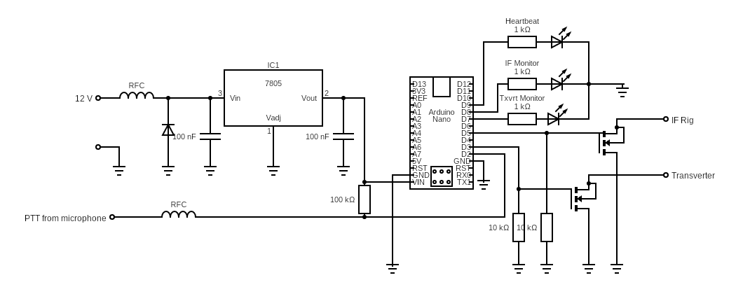
Circuit diagram of the Sequencer.

Having IC pins meant that my usual Manhattan style of construction was going to be difficult so I opted for Verobard, which brings its own problems.

The finished job. Sequencer at bottom, transverter on top.
Most of the RF getting into the microphone was solved using a metal case, screened microphone cable and a 0.1uF decoupling capacitor where the PTT entered the transverter.
The current version of the software is available on GitHub.