Zip Cord Transmission Lines and Baluns
An Analysis of a Low Cost Speaker Wire with
Common Mode Chokes as a High Frequency Transmission
Line
by Dr. Carol F. Milazzo, KP4MD (posted 25 September 2010)
E-mail: [email protected]
SUMMARY
This article describes an application of a low cost
speaker wire zip cord with common mode current chokes as
a high frequency transmission line.
INTRODUCTION
In Computer Assisted Low Profile
Antenna Modeling II1, I described the
design of a 40 meter full wave horizontal loop antenna
using speaker wire as a balanced transmission line.
Despite its lower power capacity and higher attenuation
per unit length than some coaxial cables, a short run of
dual conductor speaker wire used as a parallel
transmission line is lighter, less visible, more easily
available and economical. Speaker wire is also very easily wound on a
ferrite toroid core to form a common mode choke or 1:1
current balun. Hall2, Parmley3,
and Wiesen4 have also discussed and
characterized the use of zip cords as transmission lines.
|
 CONTENTS
|
DECREASING FEED LINE LOSS - 04 December 2010
Originally, a 40 foot roll of 24AWG speaker wire (Figure
1) was used as the transmission line. Its
theoretical calculated DC resistance was compared to its
measured resistance. The loop antenna was made of
CTI-20 gauge stranded wire with a resistance specification
of 8.63 ohms per 1000 feet, and typical 24 gauge stranded
copper wire (7/32) is listed as 23.3 ohms per 1000 feet.
The calculated total DC resistance at the transmitter end
of the 40 foot 24 gauge zip cord feed line attached to the
loop antenna would be (140'/1000' x 8.63) + (80'/1000' x
23.3) or 3.1 ohms. The actual measured DC resistance was
7.7 ohms! I confirmed this after taking down the 40
foot zip cord feed line, twisting the wires at the far end
together and measuring 6.2 ohms for the entire 80 foot
length of wire. This raised my concern for I2R
losses. A 100 watt transmission to approximately 100 ohm
impedance would produce radio frequency currents on the
order of one ampere, and approximately 6 watts of the
power would be wasted as heat in the feed line. For this
reason, I replaced the 24 gauge speaker wire with 36 feet
(11 m) of Pfanstiehl
18-gauge AS-18/50Z speaker wire (Figure 2). An MFJ-202B RX noise
bridge was used to measure this zip cord's
characteristic impedance, velocity factor, and matched
line attenuation listed in Table 1 and in the Transmission
Lines Details program plots in Figures 3 through 5.5
The attenuation of the 36 foot feed line was then 1.5 dB
at 7 MHz (comparable to RG-174/U at 1/3 of the cost) with
a total measured antenna system DC resistance of 2.5 ohms
with only 1 ohm due to feed line resistance.
The speaker wire performed most satisfactorily with low standing wave ratios on frequencies
14 MHz and below. It exhibited increasing loss above 14 MHz and significant dielectric loss at high standing wave ratios. |

|
 |
Figure
1. Original Feed Line
Uninex 24AWG
Speaker Wire
|
Figure
2. Replacement -
Pfanstiehl 18AWG
AS-18/50Z Speaker Wire
|

|

|

|
Figure
3. Characteristic impedance Z0 vs.
frequency
|
Figure 4. Velocity factor
vs. frequency
|
Figure
5. Attenuation vs. frequency
|
Table 1. Pfanstiehl 18-gauge AS-18/50Z
speaker wire attenuation vs. frequency
AS-18/50Z Speaker Wire
Attenuation vs. Frequency Z0=105Ω VF=0.69
|
Frequency MHz
|
1.8
|
3.5
|
5.3
|
7
|
10.1
|
14
|
18.1
|
21
|
24.9
|
28
|
50
|
| Attenuation dB/35' |
0.7
|
1.0
|
1.3
|
1.5
|
1.8
|
2.1
|
2.4
|
2.5
|
2.8
|
2.9
|
3.9
|
Attenuation dB/100'
|
2.1
|
2.9
|
3.6
|
4.1
|
5.0
|
5.9
|
6.7
|
7.2
|
7.8
|
8.3
|
11.1
|
IMPROVING BALUN PERFORMANCE
A commercially available 4:1 voltage balun (Figure 6) was
originally used for the transition between the 50 ohm
coaxial cable and the balanced speaker wire transmission
line. Lewallen6
and others have criticized the 4:1
Ruthroff (voltage) baluns7 commonly
included in commercially produced antenna tuning units as
being excessively lossy at high standing wave ratios and
susceptible to common mode radio frequency noise. (Voltage
baluns present these problems increasingly as an antenna
is operated away from its resonant frequency and is in an
asymmetrical environment that renders it an unbalanced
load). After a 10 minute contact on 18 MHz CW running 100
watts output power into the 40 meter full wave loop, my
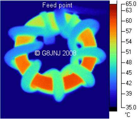
4:1 voltage balun felt quite hot to the touch. In "Baluns
and Tuners"8 Ehrenfried compared and
documented the thermal power losses in various baluns
(Figure 7). Also, while using the voltage balun,
shorting both sides of the balanced feed line together did
not quiet the receiver as expected. A significant level of
radio signals and noise were heard, representing common mode
signal pickup on the feed line and conversely implying radiation
from the feed line. |

|
|
Figure 6. Original
Balun
Lossy 4:1 Ruthroff (voltage) balun |
Figure 7. Thermal
loss in voltage balun
(from "Baluns and Tuners," Ehrenfried)
|
In their articles Common-Mode
Chokes9 and A Ham's
Guide to RFI, Ferrites, Baluns, and Audio Interfacing10
Counselman and Brown discuss the use of common mode chokes to:
- reduce undesired common mode radiation and noise pickup on
transmission lines;
- serve as a transition between balanced and unbalanced sources
and loads if needed; and,
- be configured to provide impedance transformation, if needed.
When used to transition between a balanced load and an unbalanced
source and vice versa, as Guanella11 described,
they are sometimes called current baluns or choke baluns.
Figure 37 in reference
1 shows the feed point impedance variation between 80 and 350
ohms at the resonance frequencies of 7, 14, 21 and 28 MHz,
presenting corresponding VSWRs of 1.3:1 to 3:1 to the 114 ohm
zip cord. 4:1 impedance transformation at that point would
increase the VSWR to 5.7:1 at 7 MHz; therefore no impedance
transformation in needed at the feed point. Neither is a
balun needed as both the antenna and zip cord are
balanced. Therefore, a simple common mode choke is used
there to reduce common mode radiation and noise. Likewise,
figure 54 in reference
1 shows the impedance at resonance
frequencies measured at the transmitter end of the 51 foot
transmission line varying between 45 and 120 ohms. Therefore, a simple common mode
choke would serve to reduce common mode noise and to transition
the unbalanced antenna tuning unit (ATU) to the balanced zip
cord, leaving the ATU to perform the impedance transformation to
the 50 ohm radio.
Since common mode noise and feed line radiation were such a
"pain in the derrière", I used an appropriate disposable
4" x 6" x 2" hinged plastic container to make a box (Fig. 8 and
12) for testing different baluns, with a dual binding post mounted
on one end and an SO-239 female UHF receptacle on the other.
(Given the source of the box, I named it the "H Special"—"H" for
the Henry unit of inductance, of course!) The baluns under
test would be attached to the connectors with alligator
clips. At first, I tested the 1:1 ferrite rod current balun
made previously. As superior common mode noise rejection was
observed with the toroid core baluns, no further measurements with
the ferrite rod balun were made. Then, at a local electronics
dealer, I purchased some unmarked surplus ferrite toroid cores
($.85 each) that were identified as 43 ferrite mix with the use of
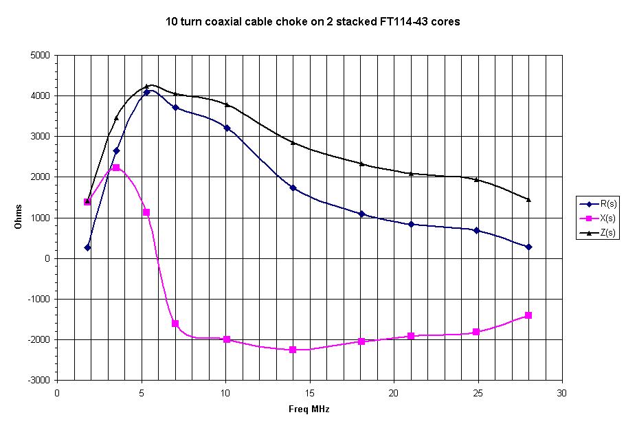
an MFJ-202B noise bridge. To make a 1:1 toroid current balun
using coaxial cable, I stacked two FT114-43 toroid cores and wound
10 turns of RG-174/U 50 ohm cable through them (Figs. 10 and
11). The inductance of this balun was approximately 200 µH
as measured at series resonance (1642 kHz) with a 47 pF
capacitor. The actual common mode impedance of all
constructed common mode chokes varied with frequency as shown in
Table 2 and Figures 19 through 21.

|

|

|

|
|
Figure 8. Homemade balun test box
|
Figure 9. 1:1 ferrite rod balun
|
Figure 10. 1:1 coaxial cable toroid choke balun.
10 turns of RG-174/U on 2 FT-114-43 cores
|
Figure 11. 1:1 toroid balun
|
Although I did not use a 4:1 current balun in the final configuration
(due to its elsewhere documented inferior common mode rejection),
figures 13 through 17 show the construction of a 4:1 Guanella
balun similar to a
design by Green12. This consisted of two
1:1 current baluns on FT140-43 toroid cores connected as shown in
Figs. 13 through 17. For these, I wound 36" lengths of the
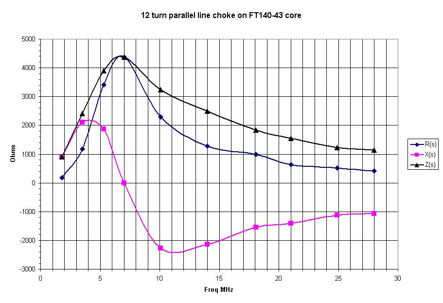
18 gauge speaker wire on each of 2 FT140-43 toroid cores.
The inductance of these chokes was 100 µH when measured in series
resonance (2320 kHz) with a 47 pF capacitor. I subsequently
measured 105 µH inductance and 1.5 pF parasitic capacitance with a
vector network analyzer.
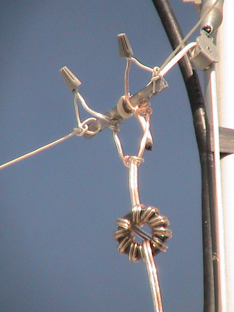
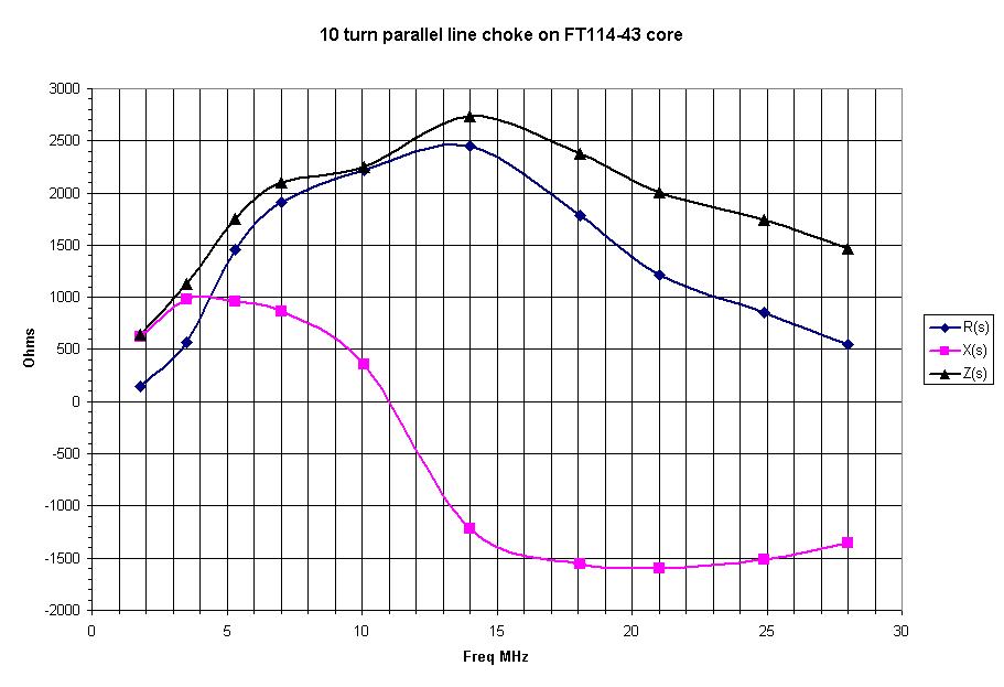
Finally, I wound 11 turns (16 inches) of 18 gauge speaker wire on
each of three FT114-43 toroid cores. The inductance of these
chokes was approximately 60 µH when measured in series resonance
(3000 kHz) with a 47 pF capacitor. On 23 January 2011 one of
these chokes (shown in Fig. 18 and as T1 in Fig. 22) was wound on
the feed line 3 inches below the antenna feed point and another
one (T2 in Fig. 22) was wound where the feed line entered through
the station window to help suppress common mode currents caused by
asymmetry of the antenna environment. These feed line chokes
might adversely affect the use of the feed line and loop as a top
loaded vertical antenna; however, this was not considered a
significant loss due to the poor performance of the antenna in
that mode. The third choke (T3 in Fig. 22) was used as a 1:1
current balun for comparison with other baluns in the balun
test box.

|
")
|

|
|
Figure 12. The "H Special" balun box
|
Fig. 13. 4:1 "Guanella" current balun schematic
diagram
|
Fig. 14. 4:1 current balun made of 18
gauge
speaker wire on two FT140-43 toroid cores
|

|

|

|
|
Fig. 15. Close-up: each core has 13 turns on each
FT140-43 core with a cross-over at the 6th
turn
|
Fig. 16. Toroid cores taped together
|
Fig. 17. 4:1 balun in box
|
Fig. 18. 1:1 choke at feed point
11 turns on FT114-43 core
|
The MFJ-202B noise bridge has a greater range than the antenna
analyzer and was used for further impedance measurements. The noise bridge was calibrated5
to increase the accuracy of measurements. Table 2 lists the
common mode impedance of each toroid choke over the frequency
range 1.8 through 28 MHz. Above 1.8 MHz all measured
impedances exceeded 1000 ohms.
Frequency
MHz
|
Coaxial cable choke on FT114-43(2)
|
Parallel line choke on FT114-43
|
Parallel line choke on FT140-43
|
Resistance
ohms
|
Reactance
ohms
|
Impedance
ohms
|
Resistance
ohms
|
Reactance
ohms
|
Impedance
ohms
|
Resistance
ohms
|
Reactance
ohms
|
Impedance
ohms
|
|
1.8 MHz
|
269
|
1389
|
1415
|
146
|
621
|
638
|
183
|
894
|
913
|
|
3.5 MHz
|
2643
|
2223
|
3454
|
570
|
976
|
1131
|
1180
|
2102
|
2411
|
|
5.3 MHz
|
4088
|
1122
|
4239
|
1461
|
960
|
1748
|
3417
|
1868
|
3894
|
|
7 MHz
|
3713
|
-1618
|
4050
|
1914
|
868
|
2102
|
4382
|
0
|
4382
|
|
10.1 MHz
|
3199
|
-2005
|
3775
|
2219
|
354
|
2247
|
2302
|
-2281
|
3241
|
|
14 MHz
|
1740
|
-2264
|
2855
|
2448
|
-1220
|
2735
|
1281
|
-2143
|
2497
|
|
18.1 MHz
|
1088
|
-2060
|
2330
|
1788
|
-1559
|
2372
|
986
|
-1549
|
1836
|
|
21 MHz
|
832
|
-1914
|
2087
|
1215
|
-1594
|
2004
|
633
|
-1407
|
1543
|
|
24.9 MHz
|
692
|
-1814
|
1942
|
859
|
-1510
|
1737
|
515
|
-1121
|
1233
|
|
28 MHz
|
289
|
-1414
|
1444
|
551
|
-1359
|
1466
|
411
|
-1066
|
1142
|
Table 2. Common mode impedance measurements of
toroid chokes vs. frequency
Figures 19 through 21 plot the common mode choke impedances
graphically.
|
|
|
|
Fig. 19. Coaxial cable FT114-43 choke impedance
vs. freq.
|
Fig. 20. Parallel line FT114-43 choke
impedance vs. freq. |
Fig. 21. Parallel line FT140-43 choke
impedance vs. freq. |
The MFJ-202B noise bridge was then used to measure impedance
through either of the 1:1 baluns or 4:1 balun with the other end
connected to the 37' feed line and loop antenna. The
standing wave ratios were calculated with reference to a 50 ohm
source. The results are listed in Table 3.
Frequency
MHz
|
Coaxial cable 1:1 balun (Fig. 54)
|
Parallel line 1:1 balun (Fig. 62)
|
Parallel line 4:1 balun (Fig. 60)
|
Resistance
ohms
|
Reactance
ohms
|
Impedance
ohms
|
SWR (50)
|
Resistance
ohms
|
Reactance
ohms
|
Impedance
ohms
|
SWR (50)
|
Resistance
ohms
|
Reactance
ohms
|
Impedance
ohms
|
SWR (50)
|
|
1.8 MHz
|
16.0
|
-98.2
|
99.5
|
15.5
|
16.0
|
-140.3
|
141.3
|
28.1
|
1.1
|
-28.9
|
28.9
|
62.2
|
|
3.5 MHz
|
12.3
|
-31.6
|
33.9
|
5.8
|
16.0
|
-23.0
|
28.0
|
3.8
|
8.5
|
6.8
|
10.9
|
6.0
|
|
5.3 MHz
|
30.9
|
63.2
|
70.3
|
4.6
|
30.9
|
63.2
|
70.3
|
4.6
|
12.3
|
32.2
|
34.4
|
5.8
|
|
7 MHz
|
57.0
|
0
|
57.0
|
1.1
|
68.2
|
12.6
|
69.4
|
1.5
|
60.7
|
35.4
|
70.3
|
1.9
|
|
10.1 MHz
|
12.3
|
-34.0
|
36.1
|
6.0
|
16.0
|
-56.3
|
58.5
|
7.3
|
27.2
|
-34.0
|
43.5
|
2.9
|
|
14 MHz
|
30.9
|
-7.9
|
31.9
|
1.7
|
34.6
|
-21.1
|
40.5
|
1.9
|
149.7
|
58.4
|
160.7
|
3.5
|
|
18.1 MHz
|
16.0
|
-11.8
|
19.9
|
3.3
|
16.0
|
-31.1
|
35.0
|
4.4
|
30.9
|
-39.1
|
49.8
|
2.9
|
|
21 MHz
|
16.0
|
5.1
|
16.8
|
3.2
|
17.9
|
-14.0
|
22.7
|
3.1
|
38.4
|
-6.8
|
39.0
|
1.4
|
|
24.9 MHz
|
45.8
|
-22.6
|
51.1
|
1.6
|
27.2
|
-28.4
|
39.3
|
2.6
|
23.4
|
-44.4
|
50.2
|
4.0
|
|
28 MHz
|
35.9
|
16.7
|
39.1
|
1.7
|
16.0
|
-9.0
|
18.4
|
3.2
|
23.4
|
-15.8
|
28.3
|
2.4
|
Table 3. Impedance measurements across
transmitter end of the 37' feed line through 1:1 and 4:1
current baluns
The impedance measurements varied in a complex manner as expected
with changes in frequency and transmission line length. The feed
line was ultimately lengthened to 51 feet (an electrical 1/2
wavelength at 7 MHz) to improve impedance matching on all desired
frequencies (see 40 Meter Loop
Antenna Transmission Line Optimization for 80 Meters and WARC
Bands). None of the current baluns heated perceptibly with
100 watts transmitted power on any frequency.
Figure 22 shows the present station antenna configuration.
With 1:1 common mode chokes at the antenna feed point and on the
output of the antenna tuning unit and the total transmission line
length adjusted to 51 feet, that is, 1/2 electrical wavelength at
7 MHz, the impedance presented was well within the range of the
antenna tuning unit on all frequencies 3.5, 7, 10, 14, 18, 21, 24
and 28 MHz.
NOISE LEVELS
The common mode signal and noise rejection were tested by shorting
both sides of the balanced feed line together and observing for
quieting of the receiver. Among the baluns, common mode signal
rejection was greatest in the current baluns and least in the 4:1
voltage balun. At 3.5 MHz, the 4:1 voltage balun showed no
measurable rejection of common mode noise at all. The toroid
current baluns with their increased common mode signal rejection
also improved reception in the low frequency and medium frequency
ranges that were previously covered by strong intermodulation
products from nearby medium frequency AM broadcast stations.
ACKNOWLEDGEMENTS
Many thanks to Dan Maguire for the Transmission Line Details
program.
REFERENCES
- Computer Assisted Low Profile
Antenna Modeling II, Milazzo, C KP4MD
- "Zip
Cord Antennas - Do They Work?", Hall, J, K1TD,
QST, March 1979, pp. 31-32.
- "Zip
Cord Antennas and Feed Lines For Portable
Applications", Parmley, W, KR8L, QST, March 2009,
pp. 34-36.
- "Portable
Antenna Notes", Wiesen, R, WD8PNL
- "Antenna System Measurements with
the MFJ-202B RX Noise Bridge", Milazzo, C, KP4MD,
March 2011.
- "Baluns:
What They Do And How They Do It", Lewallen, R,
W7EL, ARRL Antenna Compendium, Vol. 1, 1985, pp.
157-164.
- "Some Broadband Transformers",
Ruthroff, C, Proceedings of the IRE, Vol 47, No. 8,
August 1959, pp. 1337-1342.
- "Baluns
and Tuners", Ehrenfried, M, G8JNJ
- "Common-Mode
Chokes", Counselman C, W1HIS
- "A
Ham's Guide to RFI, Ferrites, Baluns, and Audio
Interfacing", Brown J, K9YC
- "New Method of Impedance
Matching in Radio-Frequency Circuits", Guanella,
G, Brown-Boverie Review, Vol 31, September 1944,
pp. 327-329.
- "Build
a Low Power 4:1 Balun", Greene, C, W1CG, QRP
Homebrewer, Vol. 8, 2002.
|
Fig. 22. The station configuration updated in 2013.
The radio is connected through RG-58/U coaxial cable jumpers
to an automatic antenna tuning unit (currently an LDG Z-11
ProII) and a 1:1 Guanella current balun (T3). A total of 4
feet (1.2 m) of the AS-18/50Z speaker wire are wound on the
the toroid cores (T1, T2 and T3) for an approximate 51 feet
(15.5 m) of total transmission line length of speaker wire
to the full wave 40 meter horizontal loop antenna. |
Return to KP4MD Home Page