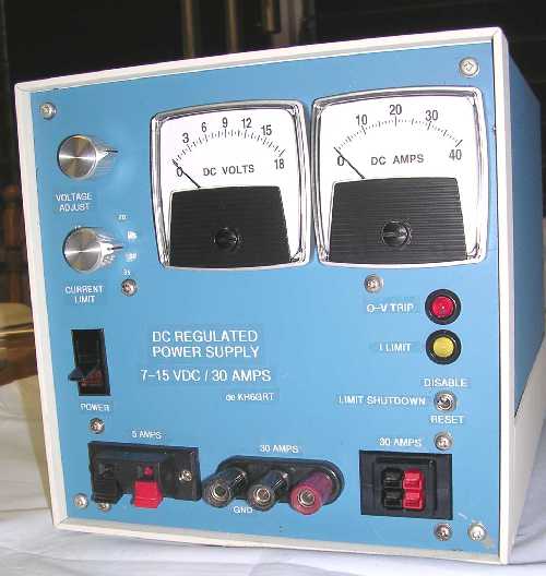
7.5-15 VDC 30 AMP REGULATED POWER SUPPLY:
A pictorial trek thru the power supply design and construction.
Pete Wokoun Sr, KH6GRT (11/2006) (12/2010) (10/2016) (12/2017)
This is a linear regulated power supply using a traditional design of a regulator chip controlling high-powered series pass transistors. Over-voltage protection is also included. No previous design was specifically used but during the early design and investigative phase I literally studied dozens of others' power supplies. I looked for circuit examples that worked, liking some ideas, rejecting others and ultimately coming up with one that worked for me and the components I had chosen to use.
The initial requirement was a 13.8 volt regulated supply capable of 20 amps continuous output. The transformer and diodes turned out ample enough to increase the final capacity to 30 amps and more. Only some voltage limitations kept it from reaching a full 40 amp ICAS capacity. The final circuit uses the almost universal LM723 IC voltage regulator which gives excellent voltage regulation. It uses three pass transistors which must be heat sinked, two series devices driven by a single driver. Very robust pass transistors were used: a pair of 2N5685 driven by a 2N5631. Each 2N5685 has a 300 watt power dissipation rating, a maximum 392 degree Farenheit junction temperature (200 degrees Centigrade), and a maximum continuous collector current of 50 amps. With an output of 40 amps the driver transistor only requires 3 mA of drive from the LM723 regulator chip. Each pass transistor heatsink has a total surface area of just over 48 square inches and with the final air flow values measured have a thermal resistance of about 0.65 degrees Farenheit per watt. The diode bridge uses type 1N1186A diodes which have an average forward current rating of 40 amps and a surge rating of 800 amps. I had a Bud "Showcase" portable enclosure acquired many years ago and wanted that to house the supply. A lot of effort was expended to make everything fit into it. A well stocked junque box acquired over the years contributed a lot to holding costs down.
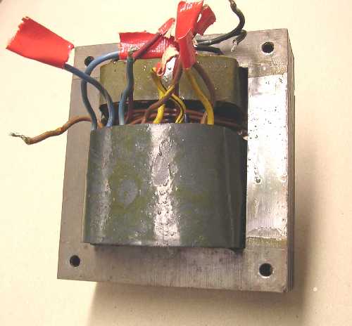
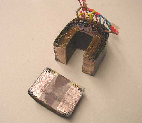
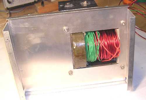
The main component was the power transformer and I didn't have one that would exactly work. I didn't want to buy a new one so it looked like I'd have to rewind one, not an entirely new experience for me. Once I had a working transformer then I'd get further into designing and building the supply. The old transformer I selected had separate primary and secondary windings on a center core.
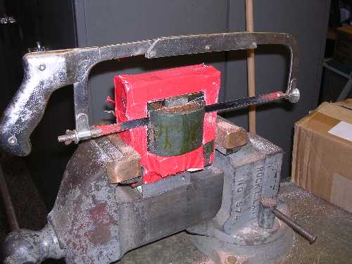
Since this transformer had a large area available for rewinding a secondary I decided to try rewinding the secondary around the core instead of disassembling the core and using a separate bobbin. So that secondary winding had to come off.
Cutting that secondary winding off.
Test coil and load resistor on the transformer core to determine just what its characteristics are.
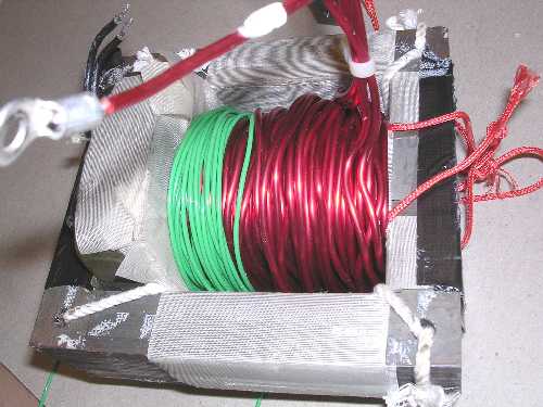
The new secondaries consisted of two windings of #10 enameled wire, each 38 turns, that are eventually paralleled. That is the red wire. The green wire is a 25 turn secondary used to power the fans.
In the end, winding that double coil of #10 wire was a physically challenging task, to say the least. Disassembling the core now seems like the way I should have gone. But eventually I had a usable transformer in-hand.
Playing around with many styles and configurations of heat sinks for the pass transistors and trying to decide if I could dissipate enough heat took a lot of hours. The reason for dissipating lots of heat stems from the fact that I wanted to make the supply voltage adjustable from 'more than 12' to 'less than 12' volts. If the supply is made much more than 12 volts, when you use it at much less than 12 volts at high current. all that extra voltage and current is dissipated as heat. At the limit, for a short circuit condition, all the voltage and current of the supply is being dissipated as heat which can be 500-600 watts.
Working with full-size sketches and rearranging parts I finally came up with some possible physical arrangements for the heat sinks that just might work.
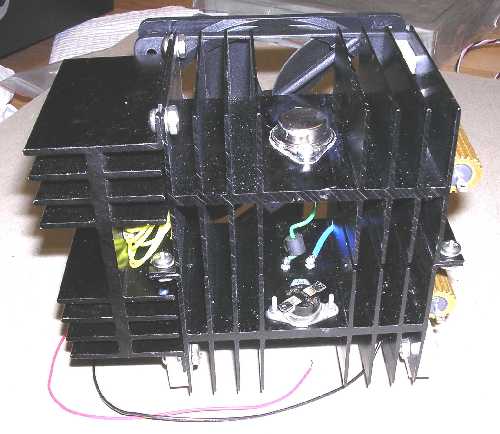
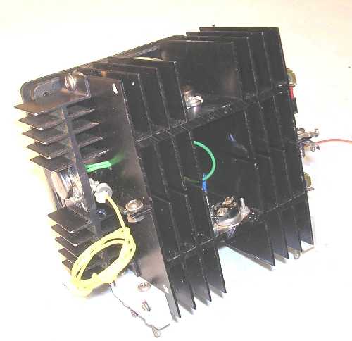
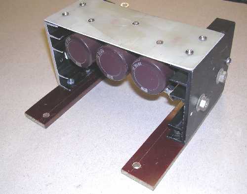
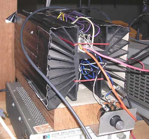
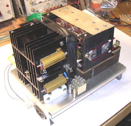
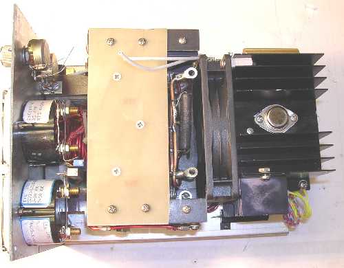
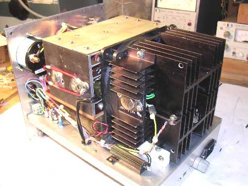
This is the heat sink arrangement I finally settled on. Two sinks are screwed together with their feet. The bottom sink is insulated and mounted off the chassis by a couple of teflon blocks. Each heat sink holds one of the pass transistors. The pass transistor 50 watt emitter balancing resistors are mounted on the right side of the sinks here. The driver transistor and its heat sink is mounted on the left side of the pass transistor heat sinks. All heat sinks are electrically connected to each other. The pass transistors and driver transistor collectors are mounted to the sinks with heat sink compound; no mica insulator is needed. That driver transistor heat sink shown is really overkill and was later changed to a smaller one.
A 120mm x 120 mm x 25 mm 12 volt DC fan is connected to the assembly on the far side here. It provides a 630 FPM air flow in its open configuration here.
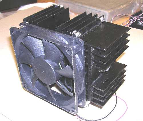
Here's a view from the fan side.
The fan has a fiberglass type frame so I didn't have to worry about shorting the heatsink to ground.
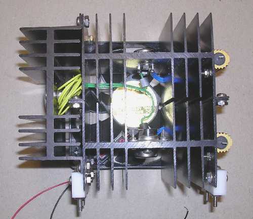
A view looking thru the heat sinks towards the fan. The teflon mounting feet are clearly visible here.
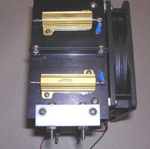
A side view showing the 0.1 ohm 50 watt pass transistor emitter balancing resistors.
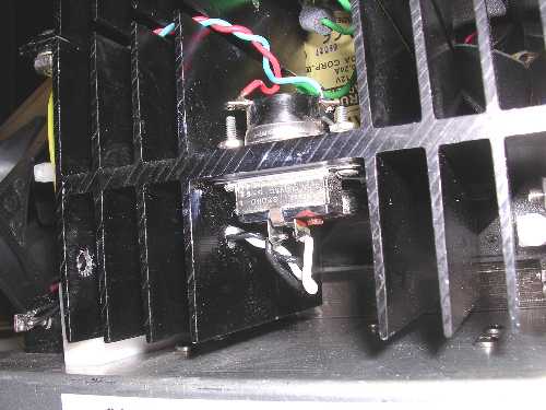
Here's the heat sink assembly with the driver transistor heat sink changed to a smaller one. Even this one runs cool! You can clearly see the heatsink thermostat on the lower heatsink in this view. The final design has a second one installed below this one.
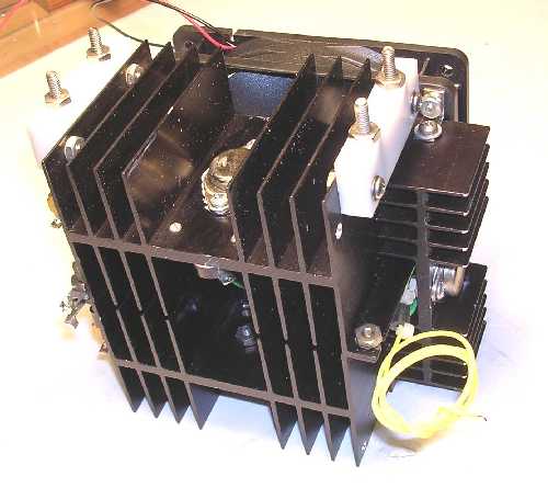
Bottom view showing the mounting feet.
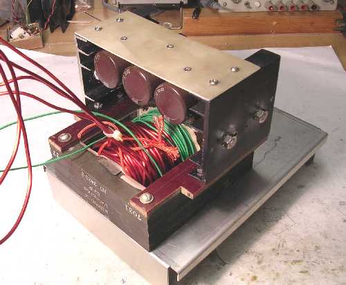
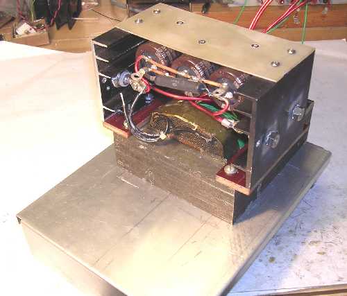
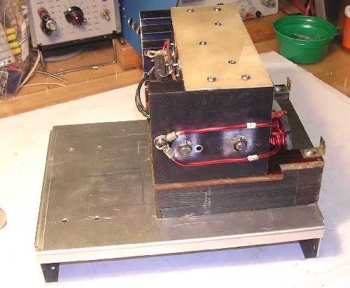
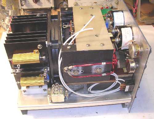
After the pass transistor heat sink assembly was moved aside, the bridge rectifier and filter capacitor assembly was worked on.
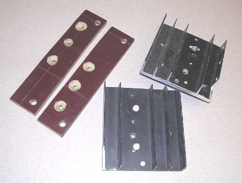
These are the diode bridge heat sinks and their insulating boards that will mount them to the top of the transformer core. These heat sinks were cut from a single larger piece.
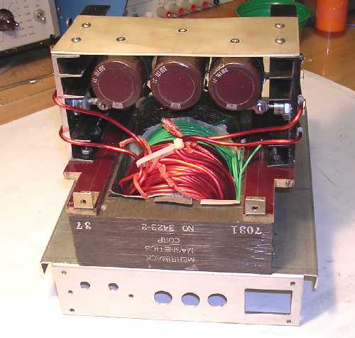
Here's the diode heat sinks mounted to their insulated mounting pieces. There's a piece of fiberglass board across their tops that holds three filter capacitors.
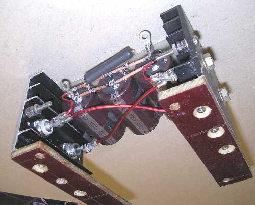
Here's an interesting view of the diode heat sinks and filter capacitors from the transformers point of view, that is, looking upward. You can see the diodes wired in their bridge configuration with connections to the filter capacitors. There's also a 1K bleeder resistor across the filter caps. All connections to the heat sinks as well as the diodes include star washers in the hardware to insure good solid connections.

Just another view of the diode / filter cap assembly.
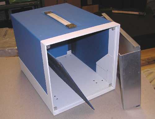
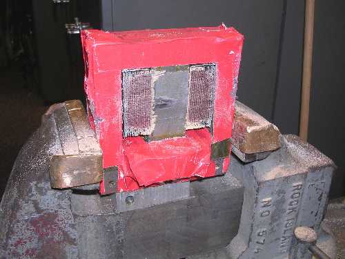
Here's a picture of that Bud "Showcase" enclosure I'm trying to get everything into.
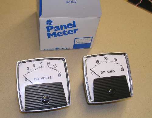
Here's the two meters I modified for the supply. They originally had 0-20 VDC scales and resistors. The resistors were removed to make them a basic 0-1 mA movement. This is what they looked like after I put new scales on them. I drew up new meter artwork using the Visio program and printed them on photo paper with a laser printer.
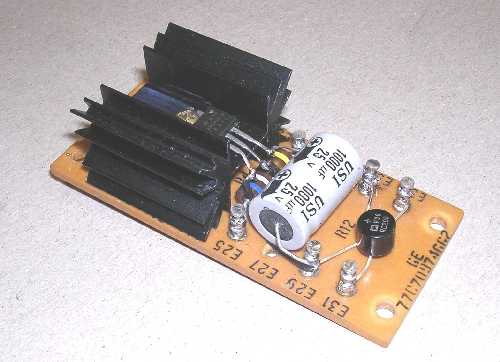
Here's what the original fan supply board looked like. Just a bridge rectifier, filter cap, and a 12 volt 3-terminal regulator. The 2 watt resistor was a series resistor with the fan that worked with the thermostat on the pass transistor heat sink. When the heatsink got warm the thermostat shorted out the resistor and the fans ran faster blowing more air.
After the pass transistor heat sink assembly, the diode / filter cap assembly, and the fan supply boards were made, they were hot wired to the transformer. A breadboard regulator circuit was built up to see if everything worked together and to work out any bugs that appeared. One bug that appeared was a tendency to oscillate up around 300 KHz when in the current limiting mode. The first time this happened it destroyed the driver and pass transistors. This was eliminated with filtering and a bunch of protection diodes.
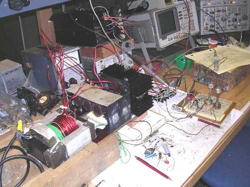
Here's my workbench with the assemblies laid out on it.
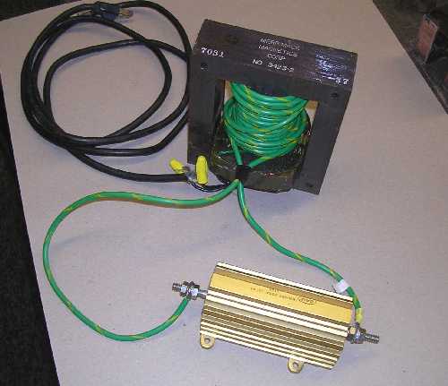
Another view of the work area from a different angle. See that 'mother of all heat sinks' in the upper part of the picture? That's a homebrew electronic load I use for testing low voltage/high current power supplies. It enables me to load the supply easily from zero to over 40 amps at up to 50 volts. I calculate it's capable of dissipating 7-800 watts continuously. It has a fan blowing air out the front. The probe in the lower right front is from an HP 428B DC clamp-on ammeter that sits on a shelf just above camera view, a VERY useful test item.
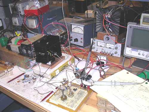
Close up of the transformer, bridge / filter cap assembly, and the pass transistor heat sink assembly in tandem being breadboarded. You can even see the fan supply board under the bridge / filter cap assembly.
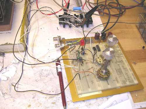
CloseUp of the breadboarded 723 regulator circuit.
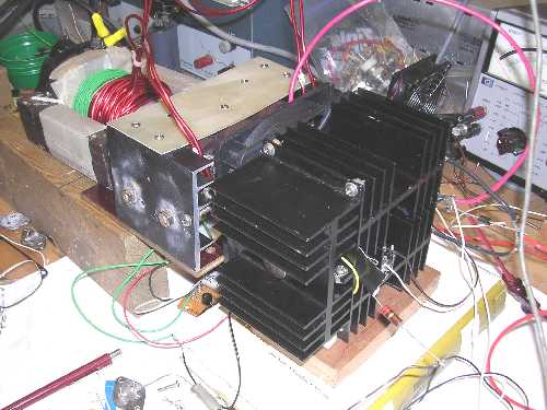
Here's a closeup of that electronic load I use. That 'mother of all heat sinks' is about 12 inches deep with a fan on the other end. With the new supply pumping out 15 volts at 30 amps which is 450 watts for over a half hour, this heat sink just got slightly warm.
After all the tweeking with the breadboard circuit was over and the regulator circuit was finalized, the regulator circuit board was assembled and tested with the laid out components. After everything electrical was working as desired, things moved to the physically-fitting-everything-into-the-enclosure phase.
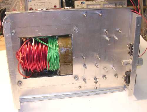
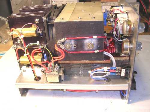
Mounting the transformer and bridge / filter cap assembly to the chassis. This view is from the front panel looking towards the rear.
A view from the rear looking towards the front of the chassis.
An underchassis view of the transformer mounting.
A side view of the transformer mounted on the chassis with the transformer leads connected to one of the bridge heat sinks. Again, star washers are used everywhere to insure a good connection thru that black anodized layer.
Another view of the transformer with the leads connected to the bridge heat sinks. The chassis also has the front panel holes cut in it. The upper transformer core has a couple angle brackets to securely hold the front panel in place.
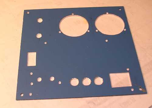
View of the front panel after cutting most of the holes and before cleaning.
Here's a view of the chassis with the heat sink assembly mounted as well as the over-voltage relay. My circuit uses a fast relay in the over-voltage protection circuit instead of the more traditional SCR that blows a series fuse. This mil surplus relay operates within 15 milli-seconds, just as fast if not faster, than blowing a fuse.
Here's an under-chassis view with the standoffs installed that hold the circuit boards.
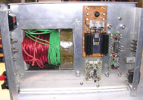
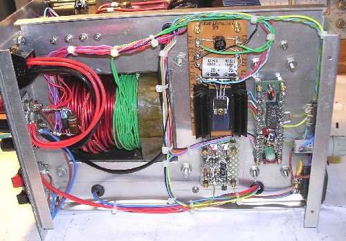
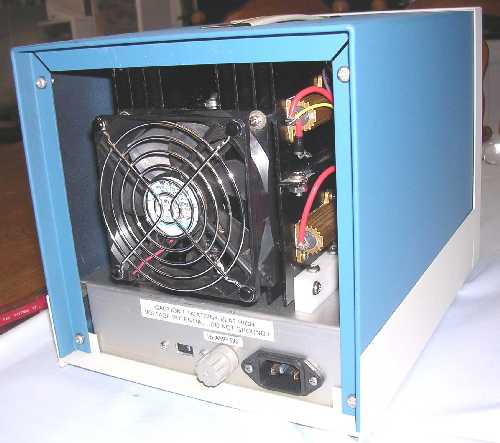
Under-chassis view with the circuit boards installed. The big one with the heat sink is the fan power supply, the one below it is the over-voltage protection circuit, and the one nearest the rear panel on the right is the regulator circuit board that holds the 723 regulator chip.
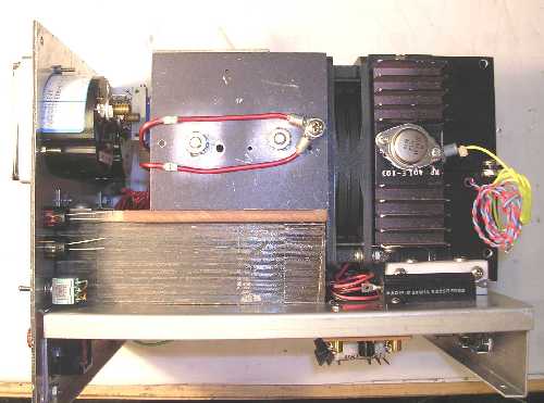
View of the right side just before the wiring started going in. That big transistor on the heat sink is the driver transistor for the pass transistors.
 .
.
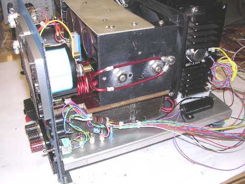
Topside view of everything just before the wiring started going in.
Left side view of everything before the wiring started going in. The two big leads are from the transformer primary now buried way down in there!
Right side view with the front panel wiring going in.
Left side view with the heavy wiring done. The heavy current leads consist of 2 #12 leads. By the way, all wiring is teflon insulated which uses silver plated copper conductors. That over-voltage relay is a 3 pole, double throw device. Each pole is rated at 30 amps and all three poles are paralleled for a 90 amp contact rating.
Right side view with all the wiring in.
Left side view with all the wiring in.
Under chassis view with the wiring in.
Front view of the supply after the wiring is installed.

Close up view of the different connectors provided on the front panel for power output. The left most terminals are spring loaded terminals that hold stripped wire leads. These are only rated to 5 amps. The center terminals are standard HP style bananna jacks rated to 30 amps. The right side connectors are the now fashionable powerpoles, a dual connector with each rated to 30 amps.
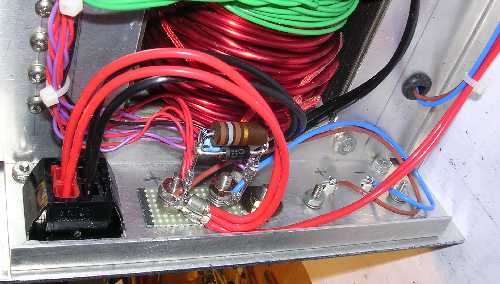
Here's a close up of the under chassis behind the front panel terminals.
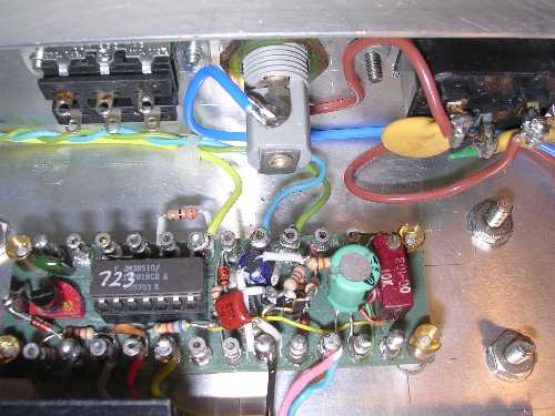
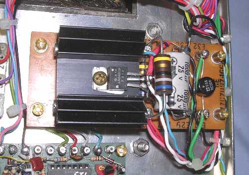
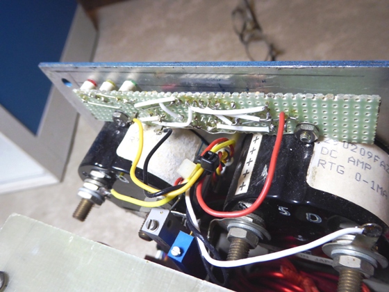
Close up view of the regulator circuit board and the rear panel. A printed circuit board would have been nicer but for one supply it was a lot quicker to just hard wire it. And I wasn't sure of any changes after final testing.
One thing about my 723 regulator circuit: the manufacturers recommend a compensation capacitor of 470 pF. There are a couple websites where the owners almost pleaded that going more than 470 pF would cause you a fate worse than meltdown. I found I had some minor oscillation problems unless that compensation cap was at least 1200 pF. I finally settled on a 5000 pF final value.
Que sera, sera.
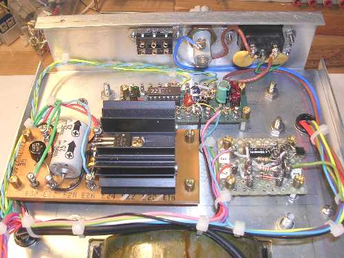
Another under chassis view showing the three circuit boards and rear panel wiring.
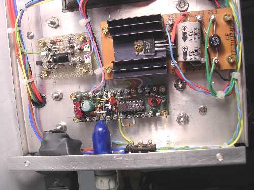
Another under chassis view after some shrink tubing and 'CapPlugs' were installed over the line voltage items to help prevent accidental shocks.
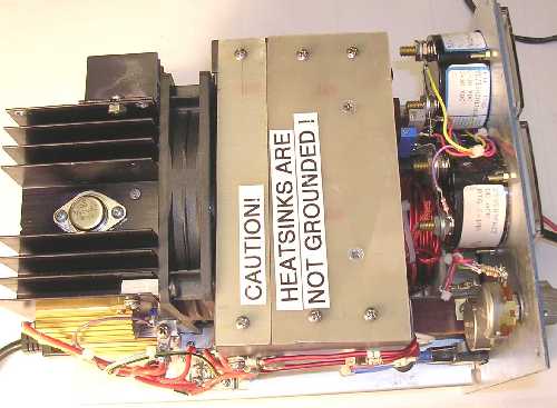
Some labels added to warn others in the future of ungrounded heat sinks. That fiberglass piece added under the 'caution!' label allowed more air to be pulled through the bridge heat sinks from behind the front panel.
 .
.
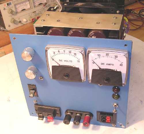
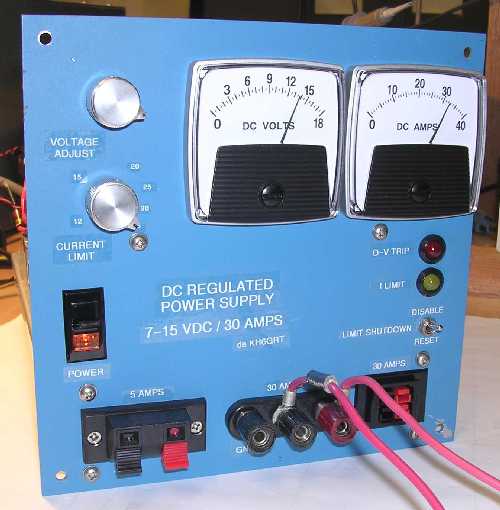
Here's a front view of the supply after some labeling was added to the controls. The supply is its final testing quietly pumping out 13.8 volts DC at about 33 amps.
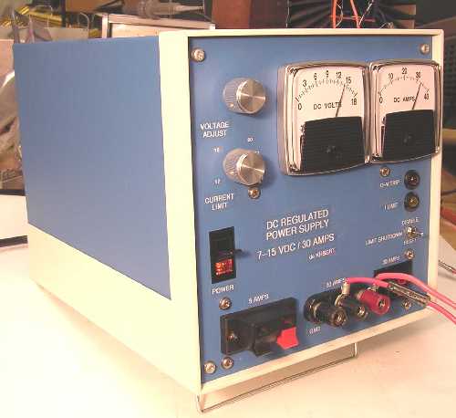
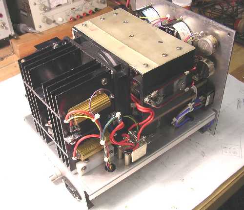
Another view of the front panel installed in the Bud enclosure during some final thermal testing.
During final testing of the supply a glitch did unexpectedly show up. It was the question of internal heat dissipation. The supply did work as designed, however, with the fan as close to the transfomer as it was, it did not produce the expected air flow as it did during breadboard testing. The benchtop air flow was a respectable 630 FPM through the heat sinks. The as-built results only produced an air flow of about 400 FPM. As a result the pass transistors were stressed at their maximum dissipation to within 14 degrees Farenheit of their maximum temperature rating. This was after I found I could increase the supplies current capacity up to 30 amps from its originally intended 20 amps without overstressing the transformer and diodes. If the supply was limited to 20 amps the pass transistors had plenty of heat margin.
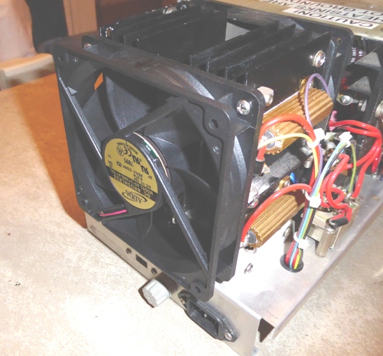
I finally decided to add another second, smaller fan at the rear of the heat sink assembly to pull out a little more heat from it. This addition increased the air flow to 950 FPM and resulted in the pass transistors having a more satisfactory 35 degree temperature margin to their maximum rating when at maximum dissipation.
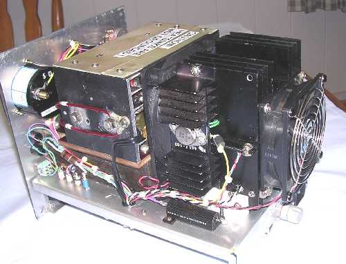
Here's a view of that second fan added behind the heat sink assembly. It projects a little more rearward than I originally planned. It projects about 1/8-inch further than the fuse holder.
Another view of the second fan showing its extension with the enclosure.
When I added the second fan I also added a second thermostat to the heat sink assembly. This gives me three fan speeds to control air flow and noise levels. Up to a heat sink temperature of 140 degrees, the fans only receive about 7 volts DC which produces an air flow about 500 FPM and very low noise levels. Above 140 degrees the fans get a full 12 volts DC producing an air flow of 850 FPM and a louder airborne noise level. When the heat sink temperature reaches 185 degrees the fans get 14 volts DC which produces an air flow of 950 FPM and even slightly higher background noise levels.
Another rearview of the second fan in the enclosure.
Closeup of the fan supply board showing a few changes to give me the three fan speeds.
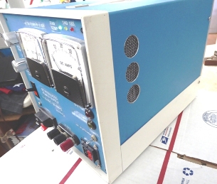
Frontal view of the completed 30 amp power supply.
Rated from 7.5 to 15 volts at 30 amps. Has auto shutdown with manual override below 10.0 volts. Hum and noise output: 200 uV @ 0 amps, increasing to 5.6 mV @ 30 amps. Current limiting adjustable from 12 to 35 amps. Automatic shutdown if output ever exceeds 16.0 volts DC.
2010 UPDATE:
After a few years of operation I felt there were a couple things that needed improvement. The first didn't involve its operation, it worked just fine. It's just that sometimes when the supply was turned off the over-voltage protector kicked in. Many times I wondered why. Probing with a 'scope showed the DC output sometimes had a short transient pulse on it which triggered the over-voltage circuit. I redesigned the over-voltage circuit but it operated the same way. I pondered that for awhile. Well, long story short: what was happening was dependent on when the power switch was opened during the AC input line voltage sinewave. At some region in the sinewave when the current was high, switching off the power caused the collapsing magnetic field in the transformer core to induce a nice voltage transient that even the filter capacitors were not able to absorb. A MOV, a Metal-Oxide-Varistor, with a 150 volt operating level installed across the primary of the power transformer absorbed this voltage pulse and now everything runs smooth, even during shutdown.
I also modified the 0-18 volt linear scale voltmeter to an expanded scale voltmeter. This expands the 10-15 volt range by 3 times and allows setting the voltage more accurately. You can see details of it in my technical section under EXPANDED SCALE VOLTMETER. I have schematics of both available below. Some front panel labels were also changed to make them more descriptive to me.
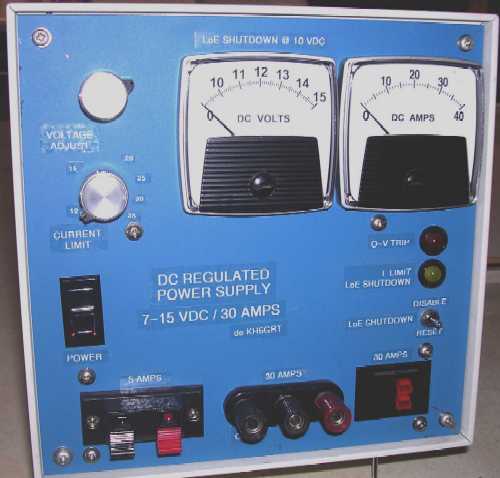
Here's the current view of the power supply, Dec. 2010.
Note the expanded scale voltmeter.
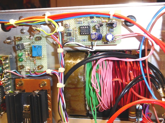
Expanded scale circuit board installed under the chassis. The pink wire is an additional transformer winding providing power for it.
2016 UPDATE:
After heavy usage of the power supply I was left wondering how hot it was getting. Wearing headphones I can't hear the fan speed. So I added some LEDs to indicate the fan speed which is related to the heat sink temperature. Circuit details are available below.
Do you know the Geico gecko? Being semi-tropical we have those cute lil critters here. In the cooler winter nights you can sometimes find one sitting on a warm power pak. One day I chased one into the power supply. I then realized I had to close up the rear to prevent them taking up residence inside.
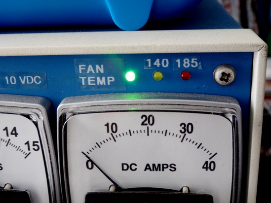
Here's the fan/temperature LEDs mounted above the ammeter.
LED circuit board squeezed in above the meters.
The rear cover to keep out the geckos.
2017 UPDATE:
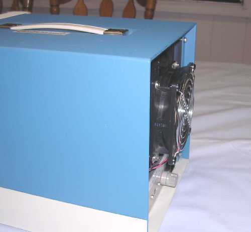
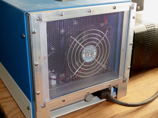
I was interested in improving the ventilation flow in the power supply even if minimally. Any improvement can be beneficial. The small 90 x 90 x 25 mm fan was removed and replaced with a 120 x 120 x 25 mm fan identical to the one between the transformer and heat sink. Also 6 holes 7/8-inch diameter were cut on the sides of the enclosure behind the front panel, 3 on each side. Previous to these mods when operating digital for extended periods the fans in the supply would cycle between low and medium speeds. Now the fans remain at low speed signifying the heat sinks never reaching 140 degrees F.
The larger 120 x 120 x 25 mm fan replacing the smaller one.

7/8-inch side ventillation holes with screening.
USE YOUR BROWSER BACK ARROW TO RETURN HERE.


![]()