CAPACITOR ESR METER WITH TONE
Used to check electrolytic capacitors for high internal resistance.
Pete Wokoun Sr., KH6GRT
May, 2014
March, 2017, Added waveform pictures
This is a follow up to Dave Chute's, KG4BZW, article 'A Series Resistance Meter Using Op Amps' in the April, 2014 issue of QST. He describes his internet inspired meter to measure the equivalent series resistance (ESR) to find faulty electrolytic capacitors. This looked like an interesting and inexpensive piece of test equipment suitable for adding to my inventory. I was reflecting how I would use the meter to test capacitors particularly surface mounted devices. If you try and hold test probes on tiny components without slipping while glancing back and forth at the meter and LED, it could be a truly frustrating experience. I present here an improvement that provides you with an audible tone representing the capacitors condition so that you can keep your eyes on the test probes and capacitor. This enables a totally sightless determination of the capacitor condition. The original meter and LED can still be used, my improvement just adds to it. Note, this meter just checks for ESR with what you might call an AC ohmmeter, it does not determine actual capacitance values.
How Is It Used?
When testing a capacitor my meter generates a CONTINUOUS TONE if the capacitor's ESR is in the acceptable good region between 0 and 3 ohms. There is a PULSATING TONE lasting 1/2 second if the ESR is in the ??? or bad regions. If the capacitor is leaky or shorted, the LED is lit and the tone changes to a CONTINUOUS PULSATING TONE. But if you (or your XYL) get tired of hearing the tone you can silence it and just use the meter and LED. The power switch has 3 positions: OFF, ON NO TONE, and ON WITH TONE.
The audible testing of a cap goes like this:
1. Turn the meter on.
2. Short the probes together and set zero to full scale.
3. Place the probes across the capacitor under test:
a. If you hear a solid tone, the cap is good; go on to the next one.
b. If you hear only a 1/2 second pulsating tone the cap is bad; it has an ESR greater than 3 ohms.
c. If you hear a continuous pulsating tone the cap is bad; it is either leaky or shorted.
|
TONE
|
CAPACITOR CONDITION
|
|
CONTINUOUS
|
GOOD
|
|
MOMENTARY PULSATING
|
BAD
|
|
CONTINUOUS PULSATING
|
BAD
|
Note that you do not have to remove the capacitor from the circuit to test it but the circuit must be de-energized. The voltage appearing across the test probes is low enough that integrated circuits, transistors, diodes and whatever are not affected. The DC component across the probes is 0.045 volts; the AC component is 0.1 volt peak-to-peak at 100 KHz dropping to zero volts when testing a good capacitor.
Range of use:
The purpose of this meter is to look for high ESR in electrolytic capacitors. You may ask if there is a range of capacitors for which this meter can be used. A 1.0 Mfd capacitor has a reactance about 1.5 ohms at 100 KHz. A perfect 1.0 Mfd capacitor will only indicate halfway into the GOOD range on the meter. Capacitors with less capacitance will read even less. Thus I believe a lower practical limit of 1-2 Mfd should be used for ESR measurements. There is no practical upper limit. However, the shorted or leaky LED indication can be used for any value capacitor.
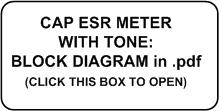
Circuit Description:
Refer to the schematic and block diagram available down at the bottom of this page for this description. Op amp U1A is configured as an astable multivibrator operating at 100 KHz. Its output goes to Q1 which drives the balanced bridge composed of resistors R6-9. By using matched resistor pairs the nodes at R6-R8 and R7-R9 are exactly equal in voltage. The output of this bridge is applied to differential amplifier U1B. With the bridge balanced the output of U1B is 0 volts DC and AC. Any AC component will be passed thru C5 to the non-inverting half-wave rectifier U2A and any DC component will be sensed by comparator U3C. If the bridge is unbalanced by only a capacitor across the test leads, the AC signal at U1B output will be rectified by U2A and the resultant DC output displayed on the meter as some amount of ESR. If the bridge unbalance includes some leakage or short the signal at U1B output will include a DC component in the positive direction. If this leakage is enough to generate a DC shift higher than the threshold voltage on the non-inverting input of U3C, the U3C output will go to a low logic level, pass thru comparator U3D and turn the LED on. U6 is a rail-to-rail virtual ground device which supplies equal positive and negative voltages referenced to its virtual ground.
To generate a constant tone which represents a good capacitor, comparator U4 senses the DC voltage across diode D4 and meter M1. It compares this voltage to the voltage at its non-inverting input which is the voltage D4 and M1 would exhibit at the 3 ohm ESR reading. If the meter is reading an ESR between 0 and 3 ohms the voltage to U4 exceeds the 3 ohm ESR reference voltage. This causes the U4 output to go to a low logic level which activates the piezo buzzer as long as the capacitor is across the test probes.
We want to generate a constant pulsating tone which represents a bad capacitor with leakage or a short, that is, with the LED on. Comparator U3A operates as an astable multivibrator operating about 10 Hz. Its output is applied to U3B. The output of U3C is a low logic level whenever the LED is on. When this low logic level is sensed by U3B it passes the 10 Hz signal to Q2. This transistor drives the piezo buzzer on and off at the 10 Hz rate as long as the LED is on. Note that this pulsating tone takes precedence over any constant tone: any leakage or short even if the meter displays in the good region results in a bad indication. This priority is handled by strobing or 'muting' the output of U4 whenever the LED is on thru resistor R31.
We now want to generate a pulsating tone for only about 1/2 second which represents a capacitor with higher than normal ESR with no leakage or short. The U6A-U6B combination is configured as a one-shot multivibrator with a delay about 1/2 second. The diode D4 and meter M1 voltage is applied to comparator U6A. Its threshold at the inverting input is a voltage representing about a 90 ohm ESR. Thus whenever the meter is measuring an ESR between 3 and 90 ohms the U6 one-shot is triggered and the output of U6B goes to a low logic level. This low logic level is applied to U3B which causes it to pass the 10 Hz signal to the piezo buzzer for 1/2 second.
Changes to KG4BZW's circuit include the LED drive circuit. I chose to use comparators U3C and U3D instead of a transistor to provide a quicker LED turn on. I also used a rail-to-rail virtual ground device U5 instead of an op amp because I received it years ago as a free sample and now had a chance to use it. I elected to omit the power-on LED to conserve some battery life. I used different op amps for U1 and U2 because I had them; they are available on ebay.
Five percent resistors are used throughout. However, the following resistor pairs are matched to 1% of each other to maintain a balanced condition in the bridge circuit: R6-R7, R8-R9, R10-R11, and R12-R13. An alternative is to use 1% resistors for these pairs.
This ESR meter draws the following currents from a fresh 9 volt battery:
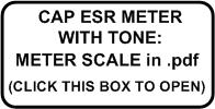
The Meter M1:
A few words on the meter you use. If you plan to remake the meter scale, the scale plate needs to be accessed. This means a sealed meter won't work. One that the front cover snaps off or, like mine, is removed by a couple screws is the way you really want to go. Then by removing a couple of very small screws inside the meter the metal scale can be removed. Slow, careful steps here will pay off in an undamaged meter. There are a couple places on my website here that show what's involved in opening up and working on meters, noteably 'http://www.qsl.net/kh6grt/page4/R390meters/pictorial/pictorial.htm' and 'http://www.qsl.net/kh6grt/page4/meterscale/meterscale.htm'. If you don't want to deal with making a new scale you could just copy mine from the file below, resize it to your meter, and paste it into yours. Another point, the metal meter scales are always symmetrical, that is, the back side is the same size and shape as the front side. I always glue my new scales onto the back side in case I want to recycle the meter back to its original look in the future. For glue, I use a glue stick which works just fine. Also, the red and green colors on my scale: colored pencils!
For calibrating the meter face I recommend using fixed resistors between 3 and 50 ohms in series with a good 50-100 uF capacitor. After zeroing the meter place this combination across the test probes to locate specific ohm points on the meter scale. This proved easier than repeated connecting and disconnecting of a variable resistor and measuring it as described by Dave in the original article. But it does require you to have a good variety of fixed resistors on hand. Once you know where the specific ESR ohm points appear on the original meter scale, you can then remake the meter scale. I remake my scales using Microsoft Vizio but there are more user friendly meter programs out there. Meter Basic by Jim Tonne W4ENE included on many recent ARRL Handbook companion software CDs is one. A copy of my meter scale is available lower down.
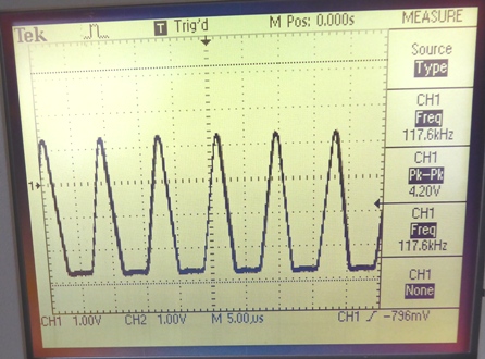
Waveforms:
Taken on a Tektronix TDS210, bandwidth limited to 20 Mhz, center horizontal line is 0 volt virtual ground, vertical scale readable on scope.
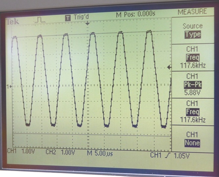
Point 1: U1A, pin 7, output of 100 Khz oscillator.
Actual: 5.88 volts peak-to-peak, 117.6 Khz, about -2.5 volts to +3.1 volts.
Op Amps like a 1458 may not work as this oscillator. They don't have enough high frequency gain. The 75558s I used are just marginal. Better would be op amps with a higher frequency large voltage swing.
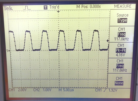
Point 2: Q1 Collector, 100 Khz output to bridge.
Actual: 4.16 volts peak-to-peak.
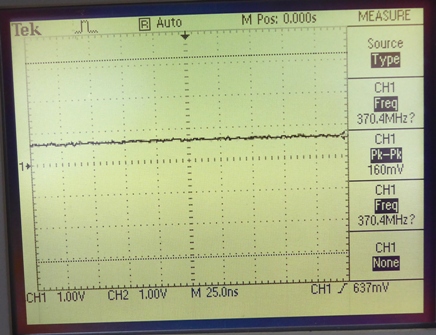
Point 3: U1B, pin 2 and pin 3, inputs to differential amp, also junctions R8-R10 and R9-R11.
Actual: about 80 mV peak-to-peak.
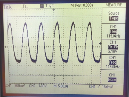
Point 4: U1B, pin 1, output of differential amp. Note: probes are SHORTED together.
Actual: 2.16 volts peak-to-peak, about -0.8 to +1.3.
Point 5: U2A, pin 1, precision rectifier, D3 anode. Note: probes are SHORTED together.
Actual: 4.2 volts peak-to-peak, about -2.6 to +1.4.
Point 6: Output of precision rectifier, D3 cathode. Note: probes are SHORTED together.
Actual: about 0.7 volts DC.
Implementation:
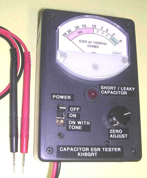
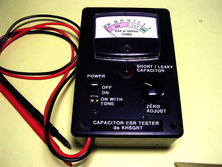
Here's the front view of the first Capacitor ESR tester with tone.
Also shown: Test probes with needle tips that work much better than the blunter standard test probes. You have to be more careful with those sharp tips but they're great for tiny surface mounted components. These probes are found in ebay stores at reasonable prices.
The LED is a large, easy-to-see 10 mm diameter red LED classified as a type T3-1/8. A rubber grommet with a 3/8" diameter hole is used to firmly hold it. Depending on the LED used resistor R22 may need tweaking to optimize brightness and minimize current drain.
With a little effort everything was fitted into a 6" x 4" x 2" plastic box.
For calibrating the meter face use fixed resistors between 3 and 50 ohms in series with a good 50 Mfd capacitor. Place this combination across the test probes to locate specific ohm points on the meter scale.
Front panel labels are P-touch label tapes by Brother. They are not as visible as they appear here with the camera flash.
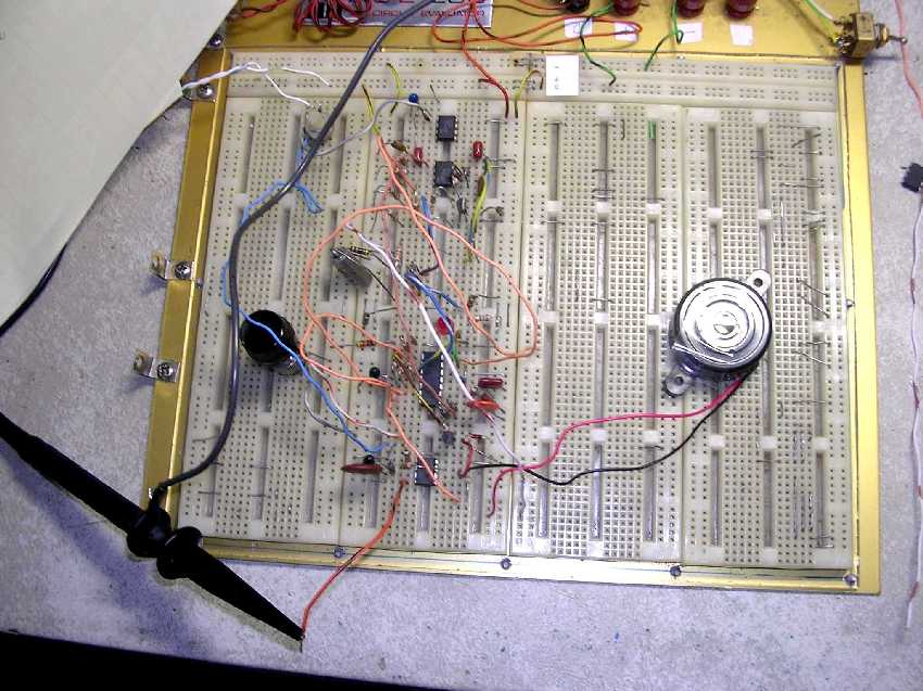
Here is the ESR meter circuit being 'breadboarded'. The bugs were all worked out before any construction started.
Parts are identified on my schematic and the parts list included below. Most are available from Mouser Electronics or Radio Shack.
The piezo buzzer, plastic case, and 9 volt battery clips are Radio Shack items (They STILL carry SOME parts!).
My circuit was assembled on prototyping board having a 0.1" x 0.1" hole grid using Vector push-in terminals and pins. Point-to-point wiring using an ancient Vector wiring pencil and 36 gauge wire with solder-thru insulation was used. The proto board is 4" x 3.6" and the circuit encompasses a 1.6" x 3.6" section at the edge of the board. The board is mounted onto the rear of the meter.
 h
h
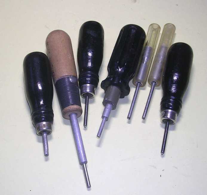
Here's some of the Vector tools I use for installing their various terminals and pins into their perf boards.
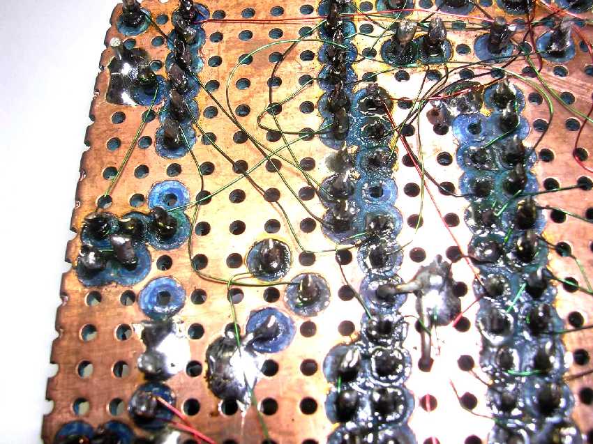
Here's a bottom-side view of the circuit board showing the point to point wiring done using an ancient Vector wiring pencil and 36 gauge wire with solder-thru insulation. Red colored wire is positive DC voltage, blue is negative voltage, and green are everything else. The copper foil was used as the virtual ground.
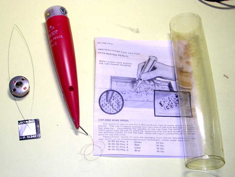
Here's a view of that old Vector type P173 wiring pencil I used for the point to point wiring on the circuit board.
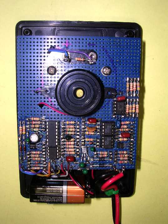
Internal view of the completed ESR meter with tone.
The big round thingy in the middle of the board is the piezo buzzer.
The proto board is 4" x 3.6". The board is mounted onto the rear of the meter with the two phillips screws.
By removing the two screws holding the board to the meter the board can be lifted and rotated exposing all components and wiring for viewing.
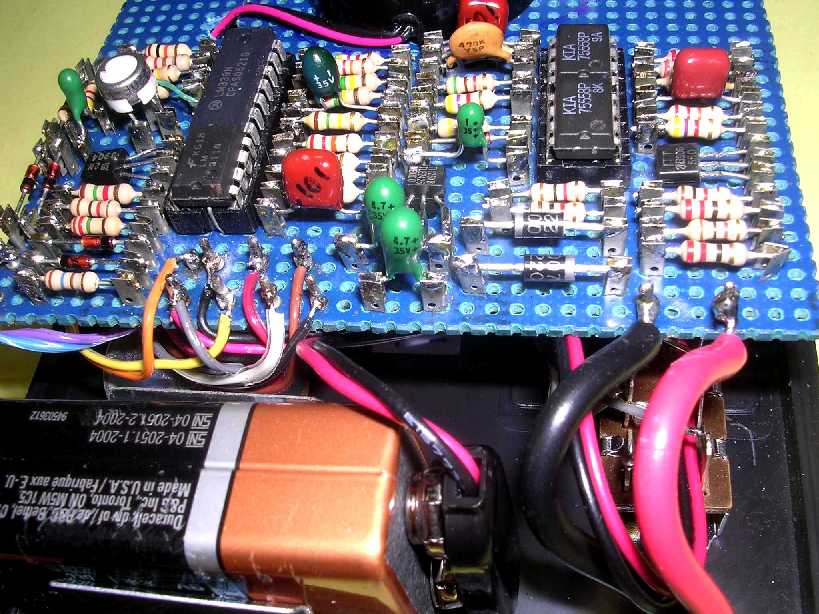
Internal view of completed ESR meter showing close up of the circuit board.
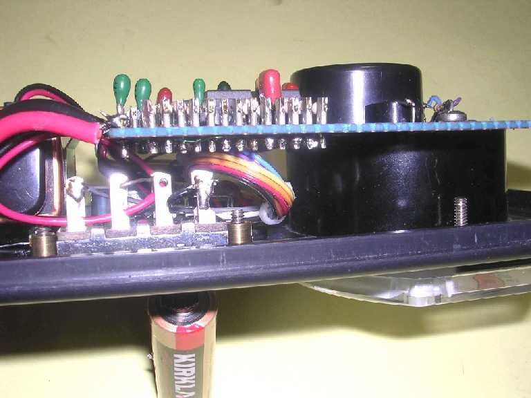
Internal side view showing the circuit board mounted on the backside of the meter. The power slide switch is shown in the foreground.
Second ESR tester built to test the printed circuit board. Different style meter (Radio Shack Micronta 50 uA movement) but everything else pretty much the same.
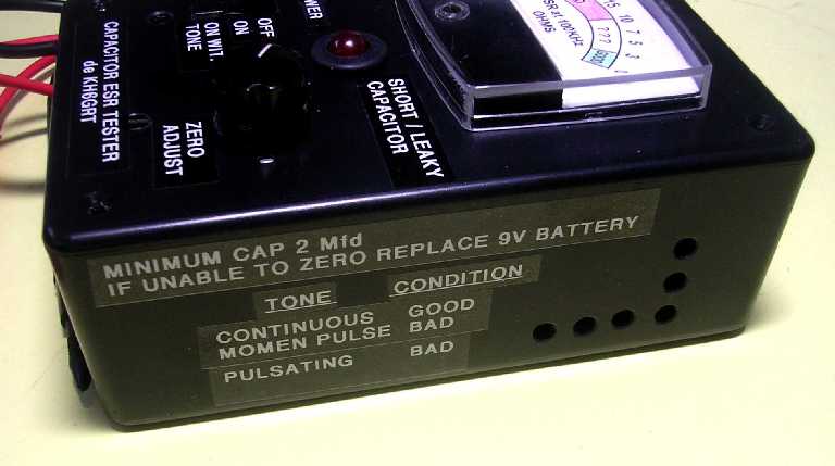
Side view of case showing nomenclature and 'sound' holes.
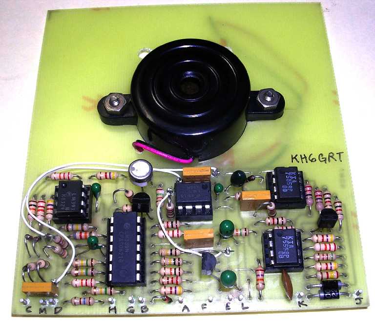
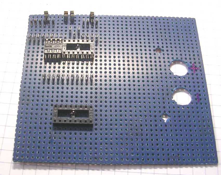
Printed circuit board with parts mounted.
Pins for the external connections are Vector type K31C inboard pins with holes drilled to 0.042" diameter. A P158 insertion tool with a D7-2 die was used to lock them onto the epoxy board. I also use a modified P133A tool to back the pins up when staking them.
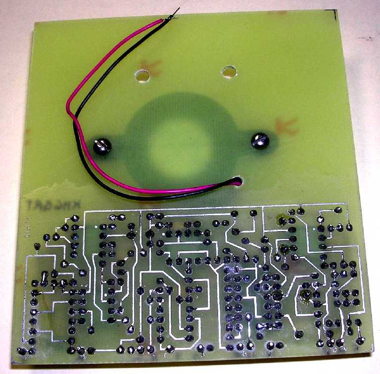
Printed circuit board, trace side. I used a 1/16" tip with a 45 watt element when soldering.
Board was made by Far Circuits.
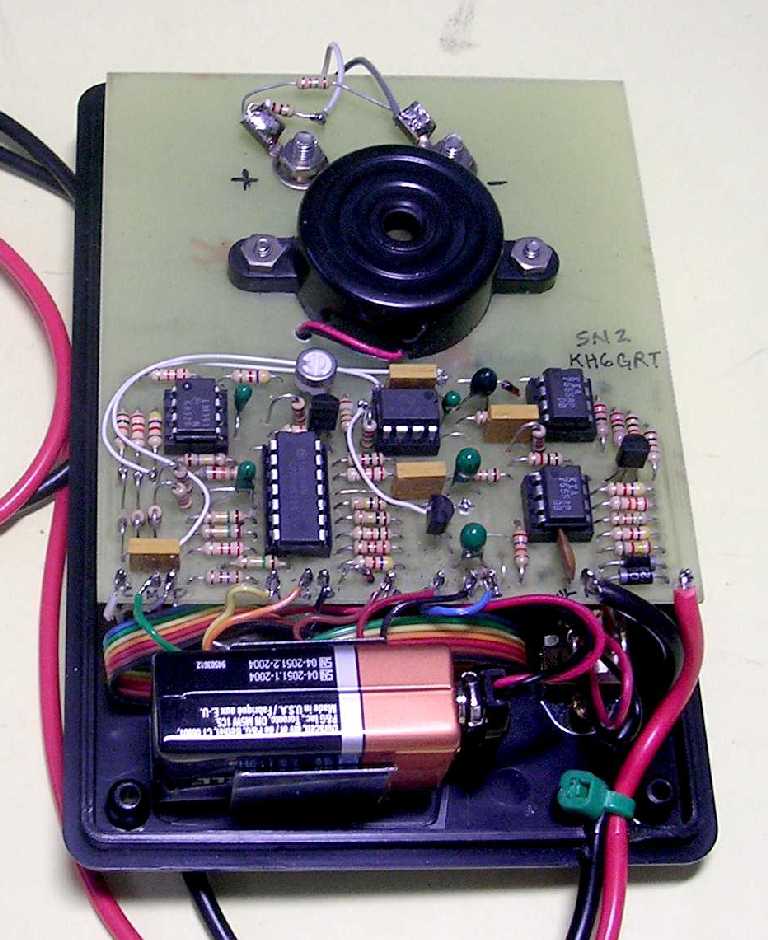
PC board mounted to rear of meter.
The meter on this unit is more sensitive than the prototype (50 uA vs. 100 uA). There are a couple resistors on the meter input to give this meter the same sensitivity and resistance so that all the tone thresholds on the comparators are the same as the prototype.
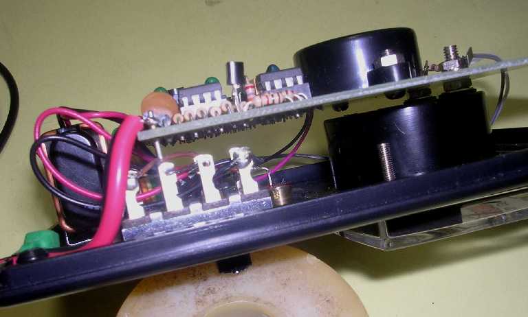
Side view of PC board mounted to meter screws.
 I
drew up artwork for a printed circuit board available here.
I
drew up artwork for a printed circuit board available here.
Thru-hole components are used but tolerances are tight. A steady hand and small soldering iron tip is needed to solder the components. If all holes are drilled to 0.031" as indicated, some may need to be enlarged slightly for larger leaded items like the 1N4007 diodes and possibly the IC sockets, if used. I would also suggest terminal pins for off-board connections.
Don't forget the jumpers shown on the component location diagram.
![]()
![]()